
Apparatus for transferring electromagnetic energy

a technology of electromagnetic energy and apparatus, applied in the direction of transformer/inductance circuit, inductance, circuit arrangement, etc., can solve the problems of link inefficiency, inability to meet the requirement of high power transfer efficiency or high data transmission rate, etc., to increase the range of operation alignment

Inactive Publication Date: 2015-01-01
CITY UNIVERSITY OF HONG KONG
View PDF7 Cites 36 Cited by
  • Summary
  • Abstract
  • Description
  • Claims
  • Application Information

AI Technical Summary

Benefits of technology

This patent describes an apparatus that can transfer electromagnetic energy using a coil arrangement consisting of a main coil and at least one auxiliary coil. This arrangement can alter the coupling between the coil and the transmitter or receiver to increase the alignment range between them. The main coil and auxiliary coil can be interchanged to maximize the overall mutual inductance. Additionally, a capacitive component can be connected to the coil arrangement to resonate with its inductance and increase the energy transfer efficiency between them.

Problems solved by technology

However, these include links may be inefficient and may not be able to satisfy the requirement of a high power transfer efficiency or high data transmission rate.

Method used


Image

  • Apparatus for transferring electromagnetic energy
  • Apparatus for transferring electromagnetic energy
  • Apparatus for transferring electromagnetic energy

Examples


Embodiment Construction

[0059]The inventors have, through their own research, trials and experiments, devised that advances in different areas, including materials science, power semiconductor technologies and proliferation of micro-fabrication and nano-fabrication facilitates inexpensive applications, like biomedical electronics, logistics and transportation, evolves research ranges from enhancing system power management to augmenting data transmission.

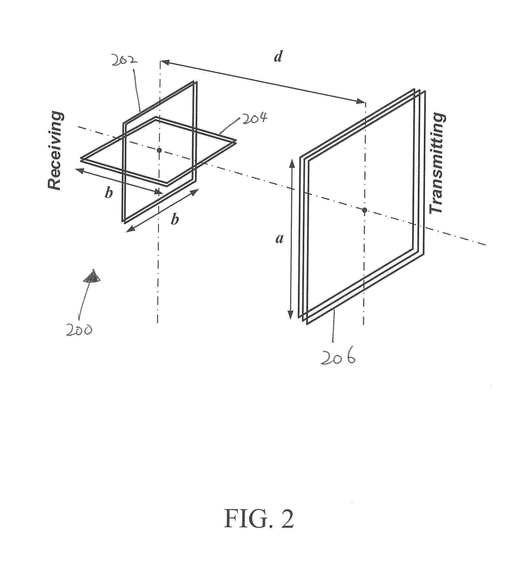
[0060]Transmitter and receiver designs have a link efficiency problem which may be determined by a fundamental “bottleneck”—fluctuations in the power transfer and link efficiency due to misaligned positions of the coupled coils. When the coils are coaxially orientated, there is magnetic coupling between the coils and thus the link efficiency are maximal. However, if the two coils are misaligned the magnetic coupling and the overall link efficiency will impair significantly.

[0061]Wireless inductive power links have been widely applied in different applicatio...


PUM

PropertyMeasurementUnit
angleaaaaaaaaaa
resistanceaaaaaaaaaa
equivalent inductanceaaaaaaaaaa

Abstract

An apparatus for transferring electromagnetic energy includes a coil arrangement operable to transmit magnetic flux to a receiver or to receive magnetic flux from a transmitter, wherein the coil arrangement includes a main coil and at least one auxiliary coil electrically combined with the main coil such that the combination of the main coil and the at least one auxiliary coil is arranged to alter an electromagnetic coupling between the coil arrangement and the transmitter or the receiver to increase an operation alignment range between the coil arrangement and the transmitter or the receiver.

Description

TECHNICAL FIELD[0001]The present invention relates to an apparatus for transferring electromagnetic energy, and particularly, although not exclusively, to a wireless inductive link arranged to transfer electromagnetic energy.BACKGROUND[0002]A wireless inductive link may be used for transmitting electrical power to a device, such as charging a device wirelessly. A wireless inductive link may also be used for wireless communication. In some devices, a wireless inductive link may operates both as an energy link to power up an end-use-device, as well as a communication link to control and retrieve data from the device, using the same set of coupled coils.[0003]A basic wireless inductive link may consist of a transmitter, a receiver, and loosely-coupled coils. Energy is transferred between the transmitter coil and the receiver coil through alternating magnetic fields. However, these include links may be inefficient and may not be able to satisfy the requirement of a high power transfer e...

Claims


Application Information

Patent Timeline
Patent Type & Authority Applications(United States)
IPC IPC(8): H01F38/14
CPCH01F38/14H02J5/005H02J50/12H02J50/005H02J50/70H02J50/90
Inventor CHUNG, SHU HUNG HENRYCHEN, NANCHOW, PO WA JEFFCHAN, LAI HANG LEANNE
Owner CITY UNIVERSITY OF HONG KONG
Learn More