Analyzer, analysis method, and analysis program

an analysis method and analysis program technology, applied in the field of analytical methods and analysis programs, can solve problems such as difficulty in general-purpose use of methods

Inactive Publication Date: 2014-12-25
OSAKA UNIV
View PDF2 Cites 5 Cited by
  • Summary
  • Abstract
  • Description
  • Claims
  • Application Information

AI Technical Summary

Benefits of technology

[0008]It is an object of the present invention to provide an analyzer, an analysis method, and an analysis program, chara...

Problems solved by technology

However, since these theorems are in the category of the integral equation theory and boundary conditi...

Method used


Image

  • Analyzer, analysis method, and analysis program
  • Analyzer, analysis method, and analysis program
  • Analyzer, analysis method, and analysis program

Examples


embodiment 1

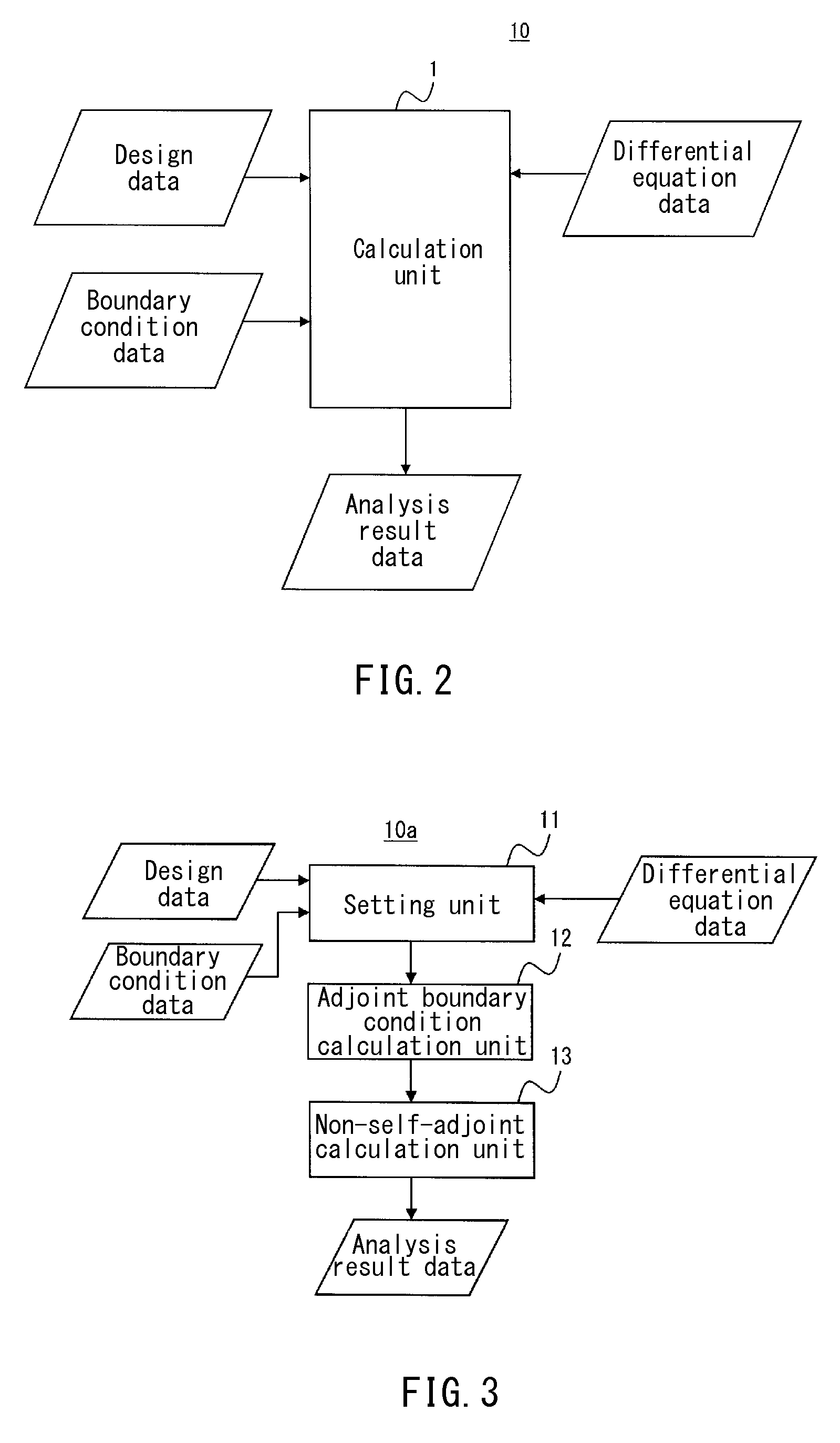
[0477]FIG. 2 is a functional block diagram showing an exemplary configuration of an analyzer of the present embodiment. The analyzer 10 (analysis system 10) shown in FIG. 2 can be formed with a computer that includes a calculation unit 1. The calculation unit 1 inputs design data of an analysis object as well as differential equation data including boundary condition data and differential operators with respect to the analysis object; calculates solutions of the differential equations of the analysis object; and outputs the same as analysis result data. Here, the calculation unit 1 calculates a solution uj by the following equation where a variation of a dual displacement ui* is given as a dual variation δui*. The following equation is the same as eq. (122).

∑i∫S(∑jLijuj-fi)·δui*s=0[Formula1]

[0478]For example, the calculation unit 1 inputs, as design data, data that show the shape and material of an analysis object, and reads data of an original differential operator Lij to be used i...

modification example 1

[0480]The calculation unit 1 may calculate a solution uj by the following equation. The following equation is identical to the above-described eq. (123). In this case, a solution of a self-adjoint problem can be calculated.

∑i∫S(∑jLijuj-fi)·δui*s=0[Formula2]

modification example 2

[0481]The calculation unit 1 can calculate a solution uj of an analysis object by the following equation, by the direct variational method. The following equation is identical to the above-described eq. (127).

∑i∫S(∑iLijuj-fi)·δ∑jLijui*s=0[Formula3]

[0482]In the calculation of a solution uj by the direct variational method, a solution such that a variation is zero may be calculated in the functional Π of the following equation.

Π≡∑i∫S(∑jLijuj-fi)2s.[Formula4]


PUM


Abstract

The present invention enables calculation of a solution of a non-self-adjoint problem represented by simultaneous differential equations. An analysis device includes: a setting unit that sets an original differential operator of an analysis object and a boundary condition of variables; an adjoint boundary condition calculation unit that calculates an adjoint boundary condition from the boundary condition; and a non-self-adjoint calculation unit that calculates a primal differential operator and a dual differential operator from the original differential operator, and determines a primal eigenfunction and a dual eigenfunction by using primal simultaneous differential equations and dual simultaneous differential equations, as well as the boundary condition and the adjoint boundary condition, thereby calculating a solution of simultaneous differential equations.

Description

TECHNICAL FIELD[0001]The present invention relates to a technique of representing a static or kinetic equilibrium of an analysis object such as a continuum by a differential equation and calculating a solution corresponding to a boundary condition, thereby analyzing a static or kinetic equilibrium or a state of the continuum.BACKGROUND ART[0002]Usually a static or kinetic equilibrium of a continuum is described by simultaneous partial differential equations, and the purpose thereof is to obtain a solution corresponding to various types of boundary conditions. In the field of engineering, a self-adjoint problem is dealt with often, and a variety of methods suitable for the same has been studied. Among these, the eigenfunction method based on Hilbert's expansion theorem is useful, and there are many examples of application of the same. In contrast, there are few studies on a non-self-adjoint problem, one of which is the eigenfunction method based on Schmidt's expansion theorem (see, f...

Claims


Application Information

Patent Timeline
IPC IPC(8): G06F17/50
CPCG06F17/5009G06F17/13G06F2111/10G06F30/20
Inventor HAYASHI, SHIGEHIRO
Owner OSAKA UNIV
Why Eureka
Try Eureka