Analysis device
an analysis device and a technology for analyzing materials, applied in the field of analysis devices, can solve the problems of inconvenient revisiting, long time, and inability to introduce analyzers in all hospitals, and achieve the effects of short time, accurate measurement, and high solubility
- Summary
- Abstract
- Description
- Claims
- Application Information
AI Technical Summary
Benefits of technology
Problems solved by technology
Method used
Image
Examples
first embodiment
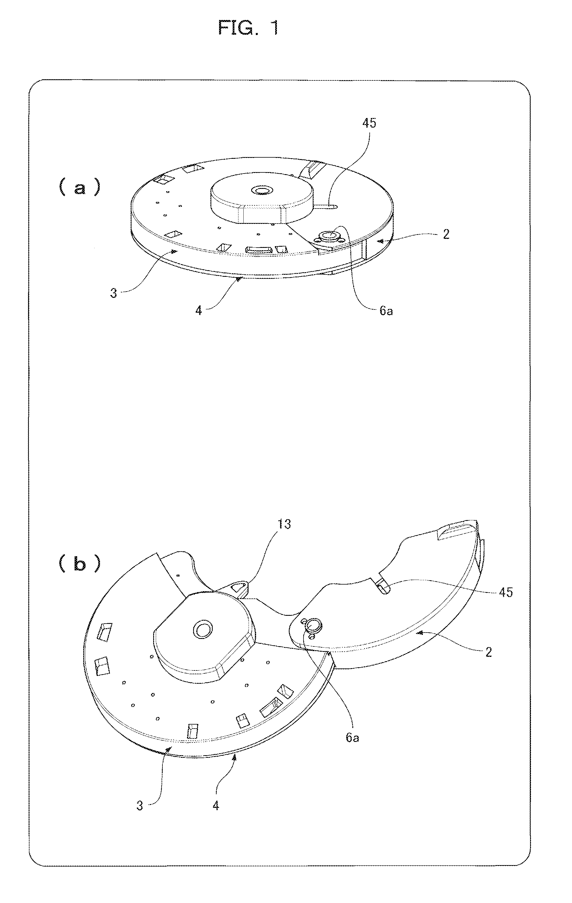
[0059]FIGS. 1 to 7 illustrate an analysis device of the present invention.
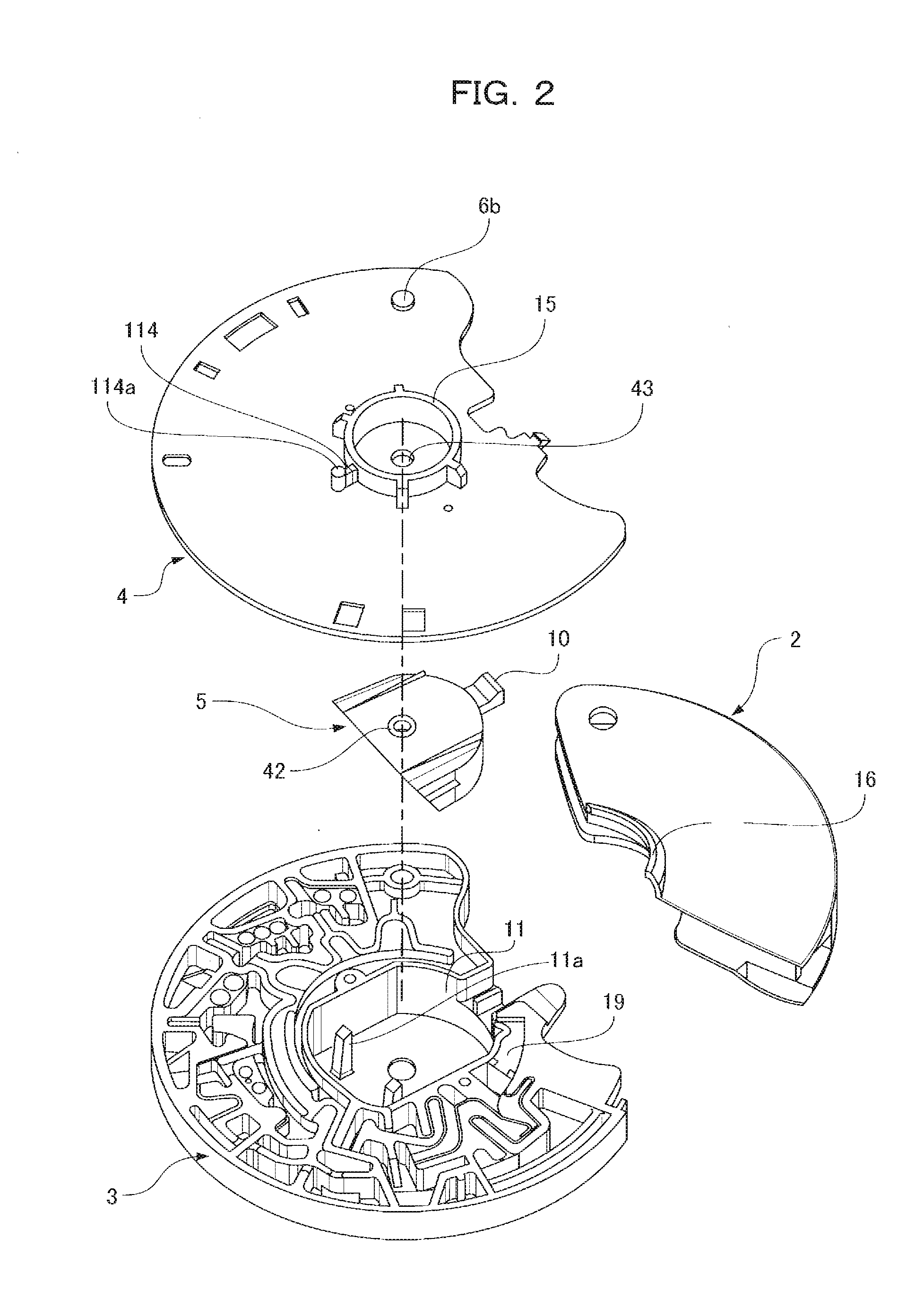
[0060]FIGS. 1(a) and 1(b) illustrate an analysis device 1 with an opened and closed protective cap 2. FIG. 2 is an exploded view of the analysis device 1 with the underside of FIG. 1(a) placed face up.
[0061]The analysis device 1 includes four components that are a base substrate 3 having a microchannel structure formed on one surface of the base substrate 3, the microchannel structure having a minutely uneven surface, a cover substrate 4 covering the surface of the base substrate 3, a diluent container 5 for retaining a diluent, and the protective cap 2 for preventing splashes of a sample liquid.
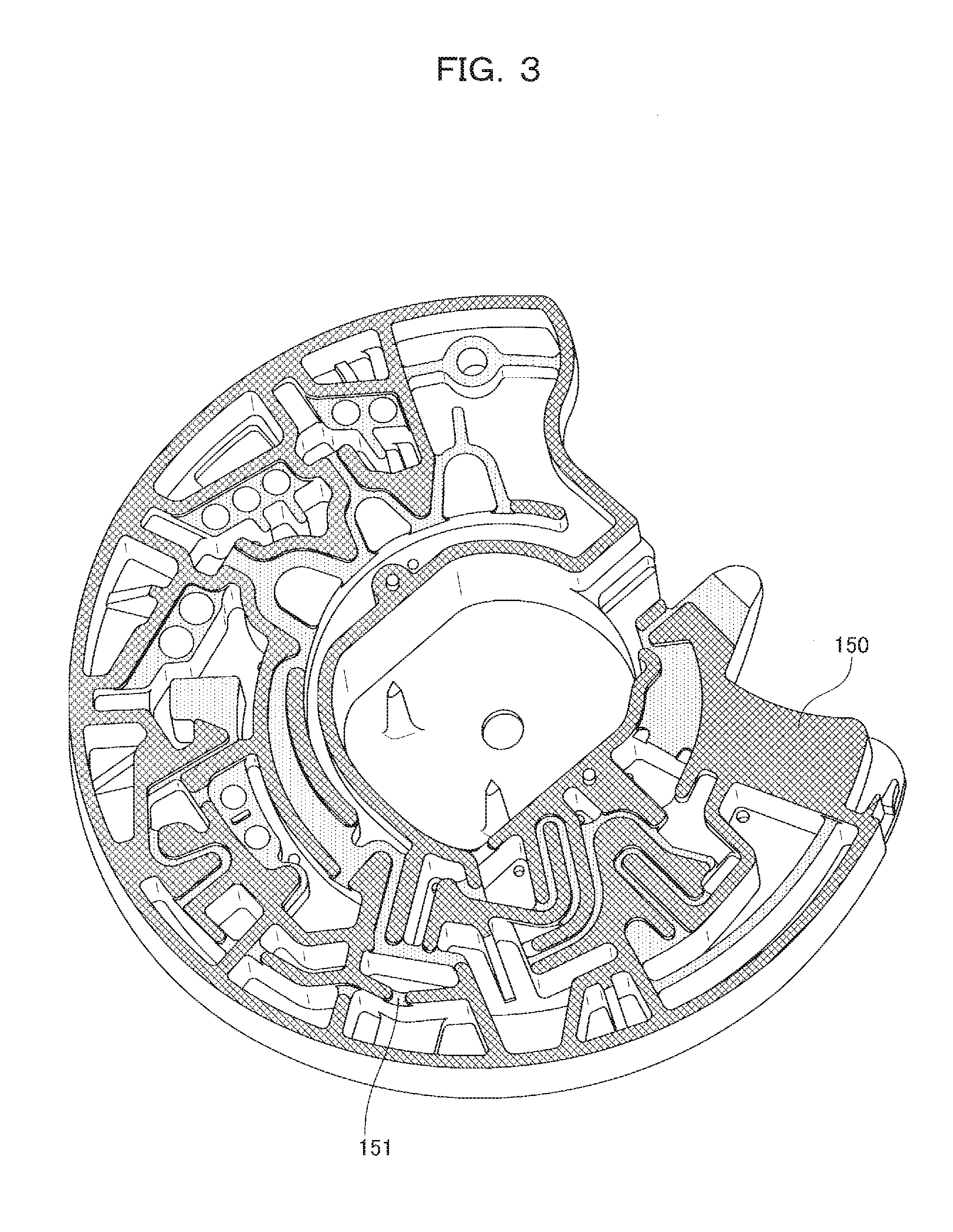
[0062]FIG. 3 illustrates the uneven surface of the base substrate 3. Hatching 150 indicates a bonded surface to the cover substrate 4. Hatching 151 indicates a point that is slightly lower than the bonded surface to the cover substrate 4 and serves as a clearance receiving a capillary force after the base substrate 3 i...
second embodiment
[0171]Reagents in the first embodiment will be specifically described below.
[0172]FIGS. 25 to 27 show a second embodiment of the present invention.
[0173]A specific example in analysis steps 1 to 7 is identical to that of the first embodiment and thus step 8 and the subsequent steps will be specifically described below. The same constituent elements as in the first embodiment will be indicated by the same reference numerals.
[0174]In step 8 after step 7, the rotation of a turntable 101 is stopped, an analysis device 1 is set at the position of FIG. 17(a), and then the turntable 101 is controlled at a frequency of 60 Hz to 120 Hz so as to oscillate the analysis device 1 by about ±1 mm, so that diluted plasma 40 retained in a reserving cavity 53 is transferred to an operation cavity 61 through a connecting section 59 by the action of a capillary force. The connecting section 59 is formed on the side wall of the reserving cavity 53 so as to be immersed under the liquid level of the dilut...
PUM
| Property | Measurement | Unit |
|---|---|---|
| angle | aaaaa | aaaaa |
| contact angle | aaaaa | aaaaa |
| contact angle | aaaaa | aaaaa |
Abstract
Description
Claims
Application Information
 - Generate Ideas
- Intellectual Property
- Life Sciences
- Materials
- Tech Scout
- Unparalleled Data Quality
- Higher Quality Content
- 60% Fewer Hallucinations
Browse by: Latest US Patents, China's latest patents, Technical Efficacy Thesaurus, Application Domain, Technology Topic, Popular Technical Reports.
© 2025 PatSnap. All rights reserved.Legal|Privacy policy|Modern Slavery Act Transparency Statement|Sitemap|About US| Contact US: help@patsnap.com


