Seal body and gas seal mechanism

a sealing mechanism and sealing body technology, applied in the direction of engine sealing, mechanical equipment, engine components, etc., can solve the problem of not allowing plastic deformation of the elastic body, and achieve the effect of restricting elastic body deformation, improving continuity of sealing and sealing durability

Inactive Publication Date: 2014-12-18
TOYOTA JIDOSHA KK
View PDF23 Cites 1 Cited by
  • Summary
  • Abstract
  • Description
  • Claims
  • Application Information

AI Technical Summary

Benefits of technology

[0007]A first aspect of the invention relates to a seal body that is used for gas seal. The seal body includes a seal main body in which a recessed groove is formed by arranging a pair of lips so that the lips face each other, an elastic body that is inserted in the recessed groove and expands the lips, and a rigid body that is installed in the elastic body and restricts deformation of the elastic body, due to narrowing of the recessed groove, within an elastic deformation range. When inversion of levels of gas pressure in gas flow passages on both sides of the seal body, i.e., back pressure, happens, the recessed groove is narrowed due to the back pressure, and the elastic body is deformed due to the narrowing of the recessed groove. Even in this case, in the seal body, the rigid body restricts the deformation within the elastic deformation range, and does not allow plastic deformation of the elastic body. Therefore, when the back pressure subsides, and the levels of the gas pressure of the gas flow passages on both sides of the seal body return to an original pressure state, i.e., forward pressure, the elastic body returns to a previous state before the back pressure happened. Therefore, according to the seal body, even if back pressure happens, once the back pressure subsides, original sealability is reproduced without any problem and the seal body is used continuously when forward pressure is recovered. Therefore, it is possible to improve continuity of sealing and seal durability. The rigid body is only installed in the elastic body, and is not related to expansion of the lips by the elastic body. Therefore, according to the seal body of this form, a size of the seal body can be similar to that of an existing seal body, and may thus be made compact.

Problems solved by technology

Even in this case, in the seal body, the rigid body restricts the deformation within the elastic deformation range, and does not allow plastic deformation of the elastic body.

Method used


Image

  • Seal body and gas seal mechanism
  • Seal body and gas seal mechanism
  • Seal body and gas seal mechanism

Examples


second embodiment

[0032]Next, a second embodiment is explained. FIG. 5 is an explanatory view showing a plan view and a sectional view of a rigid ring 30A according to another embodiment. As shown in FIG. 5, the rigid ring 30A has a slit 31 in a side wall. Therefore, when the rigid ring 30A is installed inside a spring 22, a degree of freedom for shape change is increased by the slit 31. As a result, mountability and installability of the rigid ring 30A inside the spring 22 are increased, and costs including assembly costs are reduced.

third embodiment

[0033]FIG. 6A and FIG. 6B are sectional views of a seal body 20B explaining behavior of the seal body 20B in a forward pressure sealing condition and a back pressure sealing condition. As shown in FIG. 6A and FIG. 6B, the seal body 20B includes a seal main body 21, a spring 22B, and a rigid ring 30B, similarly to the seal body 20 according to the foregoing embodiment. In the seal main body 21, the spring 22B, which is a circular-shaped coil spring, is inserted and stored in a recessed groove 21c formed by a lip 21a and a lip 21b. In short, by fitting and inserting the coil spring having a given length inside the recessed groove 21c, the spring 22B has a circular shape and is stored in the recessed groove 21c. The rigid ring 30B is a bar-shaped body having a circular section. This bar-shaped body having a given length is inserted into the spring 22B, made of a coil spring, from an appropriate location. Thus, the rigid ring 30B is installed inside the spring 22B. As shown in a back p...

fourth embodiment

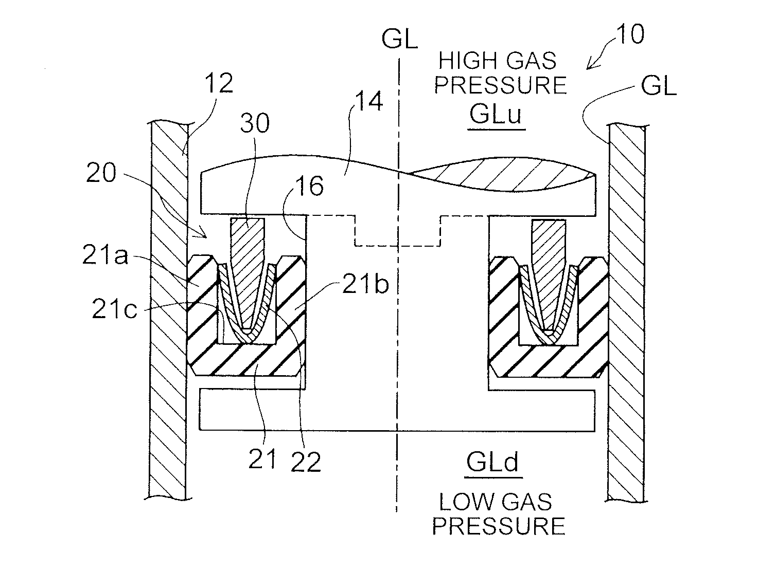
[0034]FIG. 7 is an explanatory view showing a section of a schematic structure of a gas seal mechanism 10A according to a As shown in FIG. 7, in the gas seal mechanism 10A, a shaft body 14 is a projected body, and a step part of the shaft body 14 serves as a seal body storing region 16 for a seal body 20. The gas seal mechanism 10A also includes a flange part 13 on an inner peripheral wall of the housing 12, and the flange part 13 serves as a ceiling wall of the seal body storing region 16. According to the gas seal mechanism 10A of this embodiment, plastic deformation of a spring 22 is not allowed even if back pressure occurs. Therefore, the foregoing effects are obtained. In addition, since it is only necessary to install the seal body 20 in the step part of the shaft body 14, installability of the seal body 20 is improved.

[0035]The invention is not limited to the foregoing embodiments, and may be realized in various structures without departing from the gist of the invention. Fo...


PUM


Abstract

A seal body that is used for gas seal includes a seal main body in which a recessed groove is formed by arranging a pair of lips so that the lips face each other; an elastic body that is inserted in the recessed groove and expands the lips; and a rigid body that is installed in the elastic body, and restricts deformation of the elastic body, due to narrowing of the recessed groove, within an elastic deformation range.

Description

INCORPORATION BY REFERENCE[0001]The disclosure of Japanese Patent Application No. 2013-124379 filed on Jun. 13, 2013 including the specification, drawings and abstract is incorporated herein by reference in its entirety.BACKGROUND OF THE INVENTION[0002]1. Field of the Invention[0003]The present invention relates to a seal body and a gas seal mechanism.[0004]2. Description of Related Art[0005]A seal body, in which a U-shaped seal serves as a seal main body, is able to exert high sealing performance by concurrently using a spring that expands lips. Thus, the seal body is employed as a hermetic seal for a flow passage of high-pressure gas such as high-pressure hydrogen gas in a fuel cell power generation system, a fuel cell mounting vehicle, and so on (for example, Japanese Patent Application Publication No. 2004-76870 (JP 2004-76870 A)).[0006]In a case where a seal body, which concurrently uses a spring, is incorporated in a gas flow passage for gas sealing, a gas flow passage on one ...

Claims


Application Information

Patent Timeline
Patent Type & Authority Applications(United States)
IPC IPC(8): F16J15/06F16J15/24F16J15/3212F16J15/3236
CPCF16J15/06F16J15/164F16J15/3236
Inventor UCHIMURA, CHIHIROGOTO, SOGOYAMASHITA, AKIRAINAGI, SHUSUKE
Owner TOYOTA JIDOSHA KK
Why Eureka
Try Eureka