
Endosseous implant of the improved type

a technology of endosseous implants and implants, which is applied in the field of endosseous implants of the improved type, can solve the problems of bone, inability to obtain bone, and the desired degree of so as to ensure the desired reduce the risk of bacterial proliferation, and increase the primary stability of the implan

Inactive Publication Date: 2014-12-11
IMAX3
View PDF5 Cites 0 Cited by
  • Summary
  • Abstract
  • Description
  • Claims
  • Application Information

AI Technical Summary

Benefits of technology

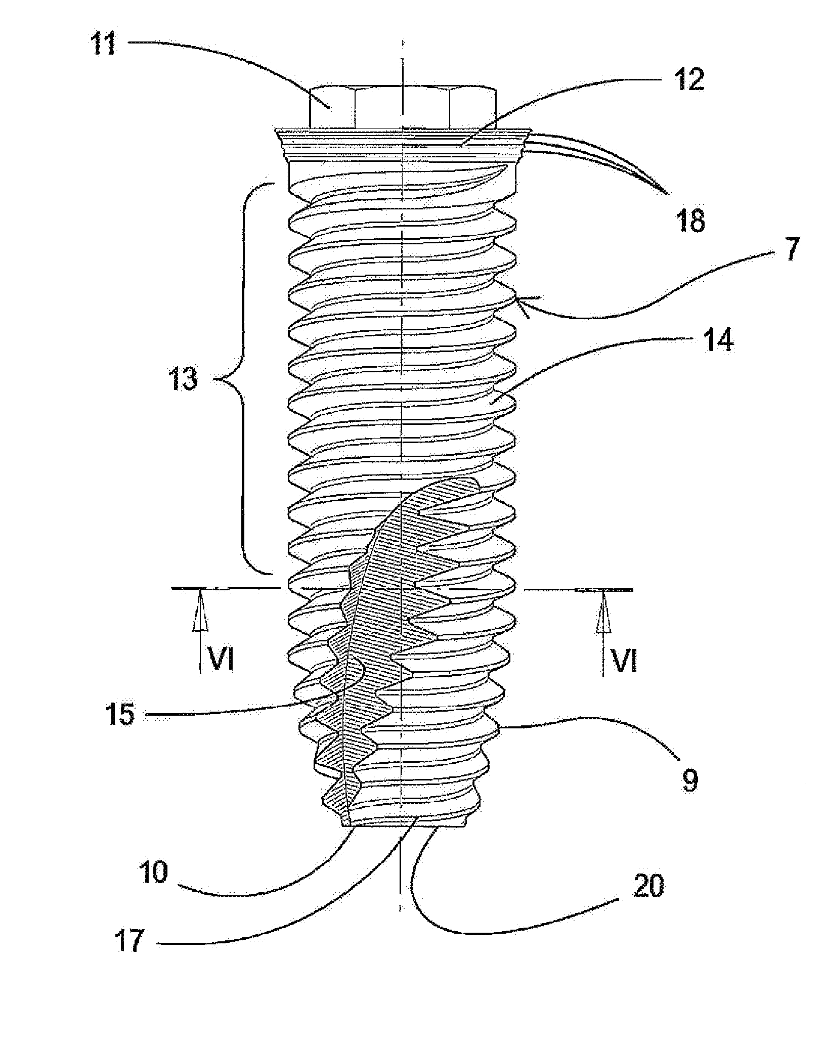
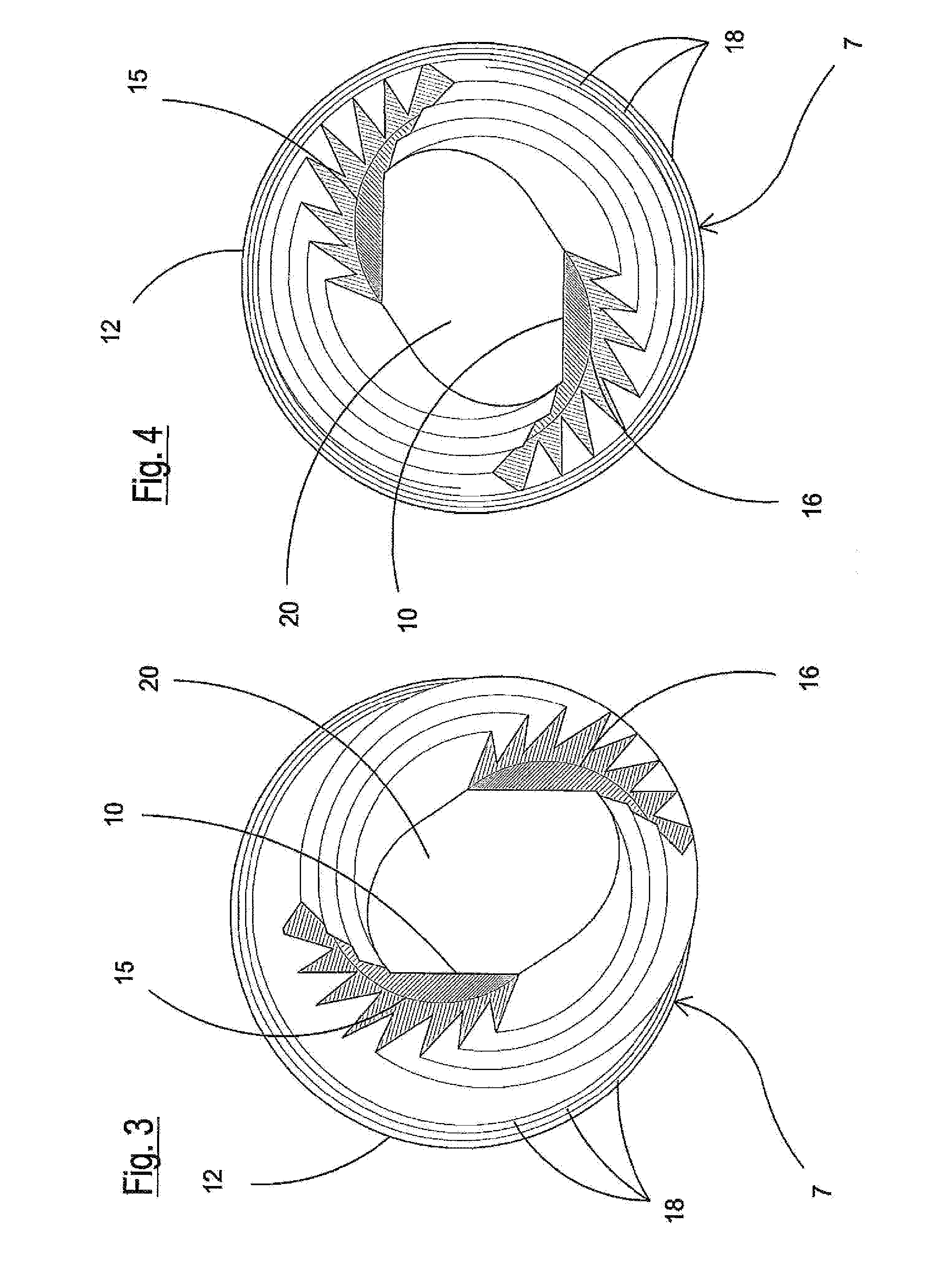
The invention provides a dental implant that has good stability, even in cases where the bone is soft or unstable. It also facilitates insertion in under-prepared locations and reduces the risk of infection. The implant has a rounded edge with millings that improve stability and prevent bone chip accumulation. The smooth finish reduces the risk of bacterial proliferation. The implant is stable enough to allow for the placement of a prosthesis and supporting the masticatory load right after placement.

Problems solved by technology

This known embodiment, however, has the disadvantage of preventing the insertion of the implant in cavities already prepared with a specific milling, as in situations in which the pre-milling has an undersized diameter with respect to the dimensions of the implant, when the implant cannot be engaged inside its milled seat.
For this reason, the desired degree of primary stability, necessary for operating on the implant at the moment of its insertion in the bone, cannot be obtained.
This requirement is particularly felt in the case of a receiving bone having a reduced mineralization, or in any case with insufficient mechanical characteristics for keeping the implant in a stable position, i.e. the condition necessary for ensuring the stability of the implant over time.
The known art also generally relates to implants having an apical area with a circular design, which increases the difficulty of inserting the implant in an undersized seat.
A further disadvantage of the known art is associated with the presence of millings at the apex, having an axial development or according to a generatrix of the body of the implant.
This known embodiment, in fact, does not allow the outflow of bone chips produced during the insertion, said chips consequently blocking the progression of the implant in the bone tissue.
This known solution, however, has the disadvantage of increasing the risk of bacterial adhesion and infection of the peri-implant tissues, resulting in a failure of the system in the medium and long term.

Method used


Image

  • Endosseous implant of the improved type
  • Endosseous implant of the improved type
  • Endosseous implant of the improved type

Examples


Embodiment Construction

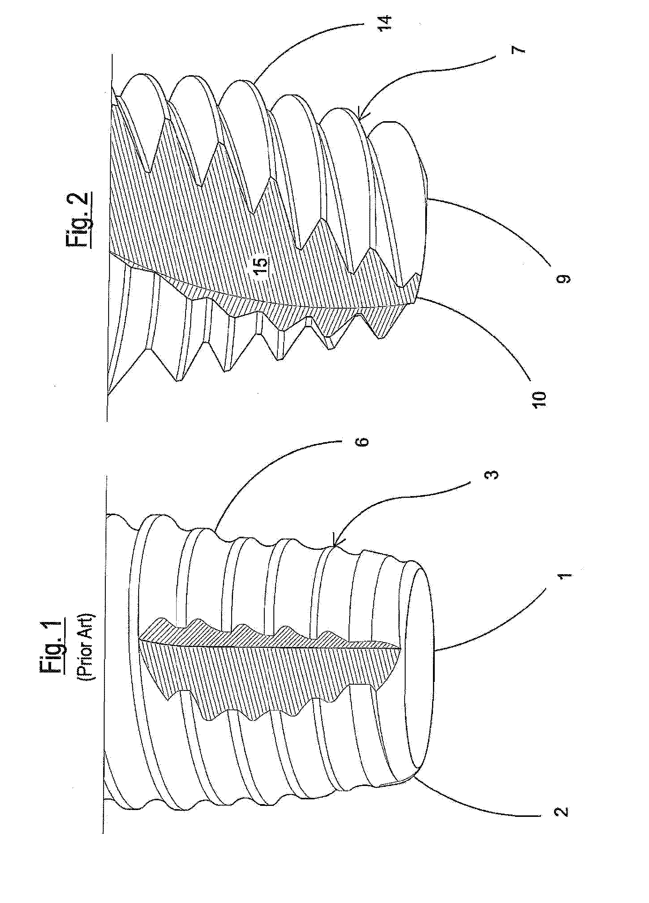
[0027]An implant 3 according to the known art is illustrated in FIG. 1 and has an apical end 1 having a rounded edge 2.

[0028]Due to the rounded edge 2 of the apex 1, and as illustrated in FIG. 9, the implant 3 of the known art having an outer diameter D1, requires, for its insertion into the bone 4, the previous formation in the bone of a corresponding circular seat 5, whose diameter D2 must correspond to the diameter D1 of the implant. This solution, however, jeopardizes the primary stability of the known implant 3 in its seat 5, above all in the case of a soft bone.

[0029]In order to compensate the described lack of primary stability, the known art provides for microroughness 6, on the outer surface of the implant 3, which, on the one hand favors the integration of the implant with the bone but, on the other hand, has the drawback of favoring the adhesion and growth of bacteria.

[0030]In order to overcome these drawbacks, the invention proposes the implant 7 of FIG. 10, which has th...


PUM


Abstract

An endosseous dental implant, of the type having a head equipped with a collar and a prosthesis connection, includes a body and an apical portion provided with an end, wherein the end has an edge with a sharp profile and a bottom having an elliptical form. In comparison to known implants with an apex having a rounded edge, an implant according to the present invention offers the advantage of improving the primary stability of the implant, also in the case of insertion in a bone of poor mechanical quality.

Description

FIELD OF THE INVENTION[0001]The present invention relates to an endosseous implant of the improved type for dental applications.BACKGROUND OF THE INVENTION[0002]The field of application of the invention relates to dental implants used for substituting missing dental elements at the level of the oral cavity. In particular, the implant substitutes the root of the tooth, thus allowing the application of a prosthesis which reproduces a tooth such as a crown.[0003]Dental implants traditionally consist of cylindrical or more specifically conical bodies, with an apex having a rounded edge or in any case not sharp. This known embodiment, however, has the disadvantage of preventing the insertion of the implant in cavities already prepared with a specific milling, as in situations in which the pre-milling has an undersized diameter with respect to the dimensions of the implant, when the implant cannot be engaged inside its milled seat.[0004]The known implants of the above described type in an...

Claims


Application Information

Patent Timeline
IPC IPC(8): A61C8/00
CPCA61C8/0024A61C8/0075A61C8/0025A61C8/0022
Inventor SIMION, MASSIMO
Owner IMAX3
Learn More