
Apparatus and methods for measuring spontaneous potential of an earth formation

Inactive Publication Date: 2014-12-11
SCHLUMBERGER TECH CORP
View PDF7 Cites 0 Cited by
  • Summary
  • Abstract
  • Description
  • Claims
  • Application Information

AI Technical Summary

Benefits of technology

The patent describes a downhole apparatus for measuring the spontaneous potential of an earth formation adjacent to a measurement electrode. The apparatus includes a downhole tool that is moveable within a borehole by tool conveyance means. The downhole tool includes a measurement electrode and downhole voltage measurement circuitry. The measurement electrode produces a potential signal representative of spontaneous potential of the earth formation adjacent it. The downhole voltage measurement circuitry measures the potential difference between the potential signal produced by the measurement electrode and a reference DC potential signal produced by the tool conveyance means. The apparatus generates spontaneous potential data that characterizes the spontaneous potential of the earth formation at different locations in the borehole. The data processing circuitry can also compensate for variations in the potential difference signals using a model. The technical effects of the patent include improved accuracy and reliability in measuring spontaneous potential in drilling and wireline logging tools.

Problems solved by technology

The drill string typically does not carry a wire that conducts DC current (voltage), and thus such TLC tools do not measure spontaneous potential.

Method used


Image

  • Apparatus and methods for measuring spontaneous potential of an earth formation
  • Apparatus and methods for measuring spontaneous potential of an earth formation
  • Apparatus and methods for measuring spontaneous potential of an earth formation

Examples


Embodiment Construction

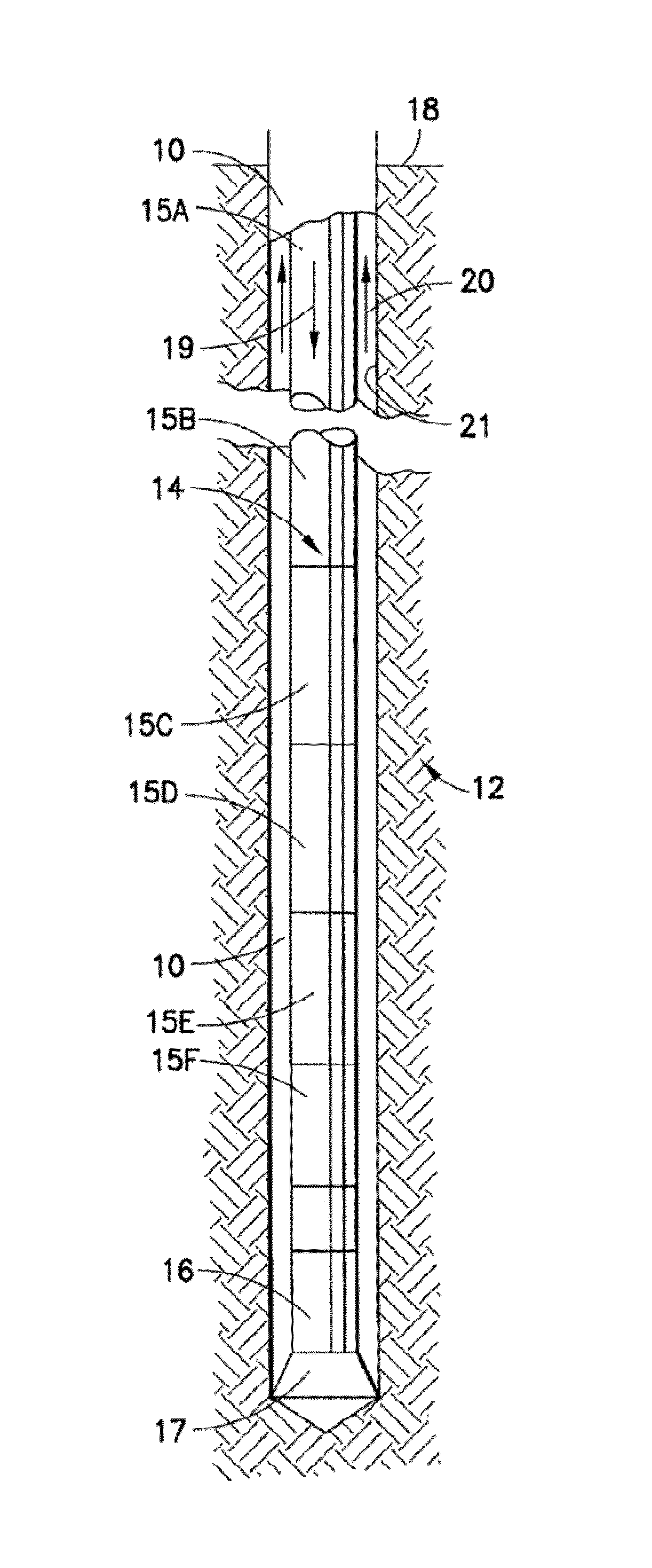
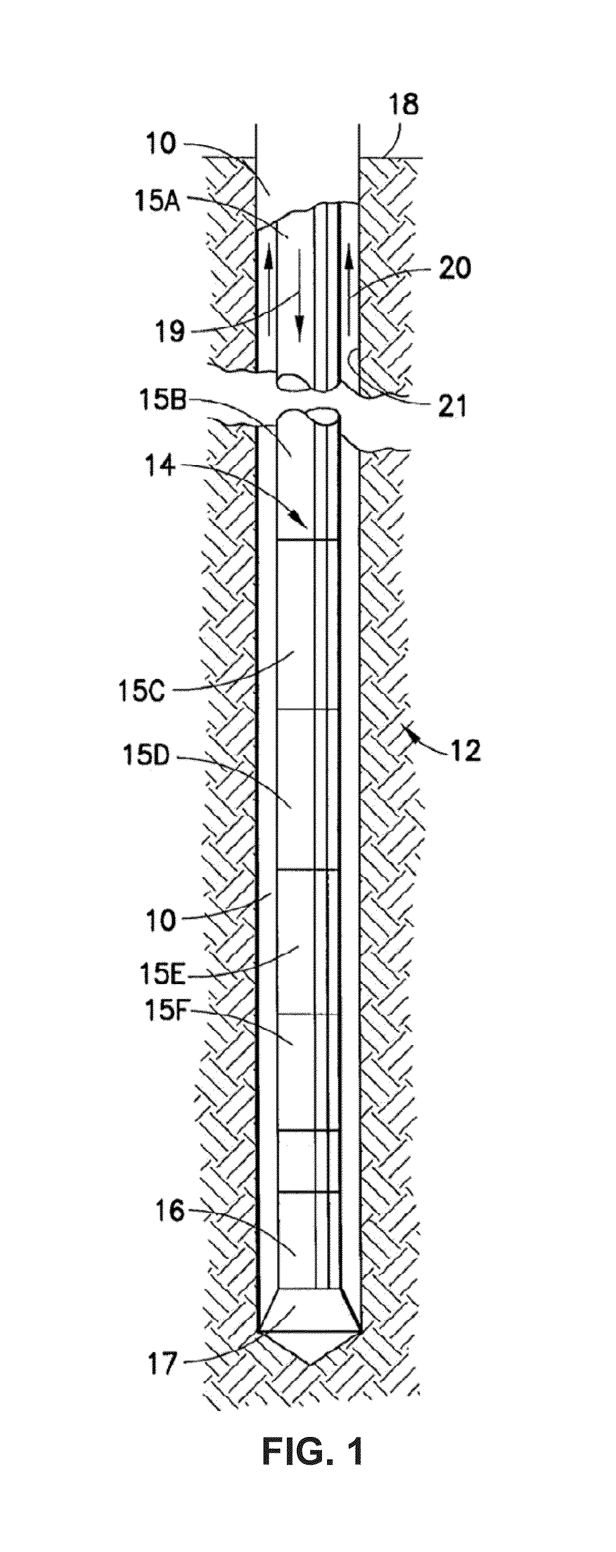
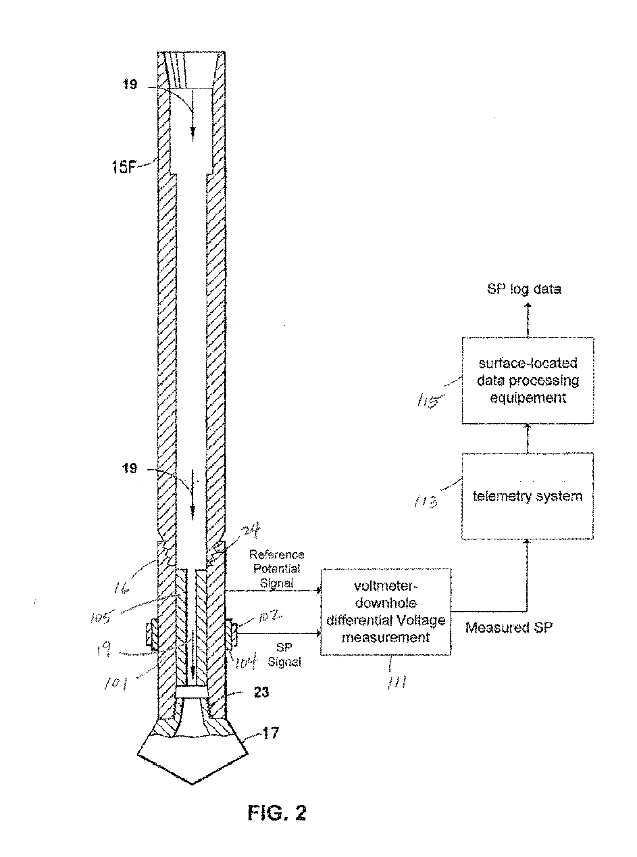
[0033]Turning now to FIG. 1, a schematic illustration of a borehole 10 drilled into a formation 12 by a rotary drilling apparatus that employs a while-drilling spontaneous potential measurement tool in accordance with the present application. The drilling apparatus includes a drill string 14 composed of a number of interconnected tubular sections (commonly referred to as “drill pipe” and shown as six sections 15A, 15B, 15C, 15D, 15E, 15F) supporting at their lower end at least one drill collar (one shown as 16). The terminal drill collar of the drill string 14 is mechanically coupled to a drill bit 17. At the surface, the drill string 14 is supported and rotated by standard apparatus (not shown), thereby rotating the drill bit 17 to advance the depth of the borehole 10.

[0034]A recirculating flow of drilling fluid or mud is utilized to lubricate the drill bit 17 and to convey drill tailings and debris to the surface 18. Accordingly, the drilling fluid is pumped down the borehole 10 a...


PUM


Abstract

An apparatus for measuring spontaneous potential (SP) of an earth formation includes a downhole tool that is moveable within a borehole by conveyance means. A portion of the conveyance means produces a reference DC potential signal. The tool includes a measurement electrode that produces a potential signal representative of SP of the earth formation. The tool also includes circuitry that measures a differential DC potential signal between the potential signal produced by the measurement electrode and the reference DC potential signal. SP data that characterizes SP of the earth formation is generated based upon the output of such circuitry. In one embodiment for a while-drilling tool, the conveyance means and tool are realized by a drill string with an insulative sleeve that supports the measurement electrode and electrically isolates the measurement electrode from the drill string. Other embodiments for while-drilling tools and tools for tough logging conditions are also described.

Description

BACKGROUND[0001]1. Field[0002]The present application relates broadly to the hydrocarbon industry. More particularly, this application relates to apparatus and methods for measuring spontaneous potential of an earth formation traversed by a borehole.[0003]2. Related Art[0004]Spontaneous potential (SP) is naturally occurring (static) electrical potential in the earth. Spontaneous potential is usually caused by charge separation in clay or other minerals, by the presence of a semipermeable interface impeding the diffusion of ions through the pore space of rocks, or by natural flow of a conducting fluid (salty water) through the rocks. Variations in spontaneous potential can be measured in wellbores to determine variations of ionic concentration in pore fluids of rocks. The magnitude of the spontaneous potential depends mainly on the salinity contrast between the drilling mud and formation water and the clay content of the permeable bed. Spontaneous potential is not measured when a non...

Claims


Application Information

Patent Timeline
IPC IPC(8): G01V3/26G01V3/04
CPCG01V3/04G01V3/265G01V3/22
Inventor CHEN, MIN-YITARVIN, JEFFREY A.LAC, ETIENNECASTON, ANDREW
Owner SCHLUMBERGER TECH CORP
Learn More