Unitary heat exchangers having integrally-formed compliant heat exchanger tubes and heat exchange systems including the same

a heat exchanger and integral technology, applied in the field of unitary heat exchangers, can solve the problems of inconvenient manufacturing process, inconvenient use, and inability to achieve favorable weight and performance characteristics, so as to reduce the cost and variability of manufacturing process, and improve the durability and life of the heat exchange system.

Active Publication Date: 2014-12-11
HONEYWELL INT INC
View PDF14 Cites 49 Cited by
  • Summary
  • Abstract
  • Description
  • Claims
  • Application Information

AI Technical Summary

Benefits of technology

The patent describes a kind of heat exchanger that has several small tubes that are all in one piece, and each tube has a bellows-like part that allows it to expand and contract. The heat exchange system using this heat exchanger can transfer heat between two fluids, and it is designed to be compact and efficient. The heat exchanger is made by a process called integrally forming the tubes, which helps to make the whole system stronger and more durable.

Problems solved by technology

Plate-fin architectures, while relatively inexpensive to manufacture, do not result in favorable weight and performance characteristics.
Tubular architectures, while relatively more efficient than plate-fin architectures, are often prohibitively expensive to manufacture.
Furthermore, conventional plate-fin and tubular architectures are susceptible to thermo-mechanical fatigue (TMF), especially at braze connections, as they do not allow adequate thermal growth and stress compliance during transient and steady state operations, reducing their service life and / or necessitating costly repairs.
For example, heat exchanger tubes in conventional heat exchangers with tubular architectures may be rigidly coupled to each other by fins or otherwise, thereby restricting relative motion and inducing detrimental stresses in the heat exchanger.

Method used


Image

  • Unitary heat exchangers having integrally-formed compliant heat exchanger tubes and heat exchange systems including the same
  • Unitary heat exchangers having integrally-formed compliant heat exchanger tubes and heat exchange systems including the same
  • Unitary heat exchangers having integrally-formed compliant heat exchanger tubes and heat exchange systems including the same

Examples


Embodiment Construction

[0028]The following detailed description is merely exemplary in nature and is not intended to limit the invention or the application and uses of the invention. As used herein, the word “exemplary” means “serving as an example, instance, or illustration.” Thus, any embodiment described herein as “exemplary” is not necessarily to be construed as preferred or advantageous over other embodiments. All of the embodiments described herein are exemplary embodiments provided to enable persons skilled in the art to make or use the invention and not to limit the scope of the invention which is defined by the claims. Furthermore, there is no intention to be bound by any expressed or implied theory presented in the preceding technical field, background, brief summary, or the following detailed description.

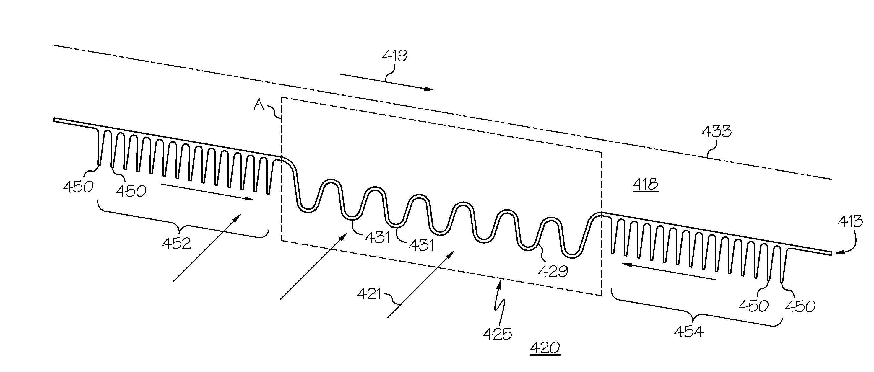
[0029]Various embodiments are directed to unitary heat exchangers having integrally-formed compliant heat exchanger tubes and heat exchange systems including the same. As used herein, the term ...


PUM

PropertyMeasurementUnit
poweraaaaaaaaaa
pressureaaaaaaaaaa
temperatureaaaaaaaaaa

Abstract

Unitary heat exchangers having integrally-formed compliant heat exchanger tubes and heat exchange systems including the same are provided. The unitary heat exchanger comprises an inlet plenum and an outlet plenum and a plurality of integrally-formed compliant heat exchanger tubes. The plurality of integrally-formed compliant heat exchanger tubes extend between and are integral with the inlet and outlet plenums to define a heat exchanger first flow passage. Each integrally-formed compliant heat exchanger tube comprises a tubular member and a plurality of integral heat transfer fins extend radially outwardly from at least one portion of the tubular member. The tubular member has a proximal tube end and a distal tube end and comprises a tubular wall having an outer wall surface and an inner wall surface.

Description

TECHNICAL FIELD[0001]The present invention generally relates to heat exchange systems, and more particularly relates to unitary heat exchangers having integrally-formed compliant heat exchanger tubes and heat exchange systems including the same.BACKGROUND[0002]Heat exchange is important to ensure machinery and engines such as gas turbine engines remain within acceptable operational parameters as well as to achieve efficient thermodynamic operation. In the field of gas turbine technology, a great deal of effort has been directed toward improving thermodynamic efficiency by operating gas turbine engines at increasing temperatures. As such, numerous heat exchange systems have been developed for directing heat within an engine to components where such heat is beneficial to the operating performance of the engine, while other heat exchange systems have been developed for directing heat away from engine components that normally cannot tolerate such high temperatures.[0003]In one example, ...

Claims


Application Information

Patent Timeline
Patent Type & Authority Applications(United States)
IPC IPC(8): F28F1/10F28F5/00
CPCF28F5/00F28F1/10F28D1/05316F28D7/16F28F1/26F28F2255/18F28D2021/0021F28F2265/26F28F2255/02F28D7/0058F28F1/006F28F1/08Y02P10/25B22F10/62B22F10/66B22F10/25B22F10/28B22F10/64B22F10/36F16L27/11
Inventor WALDMAN, DAVIDMORRIS, MARK C.GODFREY, DONALD G.
Owner HONEYWELL INT INC
Why Eureka
Try Eureka