
Procedure and facility for grain moisture control

a technology of grain moisture control and process, applied in the field of new system, can solve the problems of not being representative of the grain conditioning process and not prioritizing grain quality, and achieve the effect of simple and effective, easy and effectiv

Active Publication Date: 2014-12-11
INST NACIONAL DE TECNOLOGIA AGROPECUARIA
View PDF3 Cites 29 Cited by
  • Summary
  • Abstract
  • Description
  • Claims
  • Application Information

AI Technical Summary

Benefits of technology

The present invention provides a facility to control the moisture of a bulk material stored in a container silo. This is done by using a flat base floor and an elevated floor with a plurality of holes, which creates an air chamber between the two floors and an air heating means connected prior to the air flow into the air chamber. The air blowing means uses a centrifugal fan and a gas burner. The invention also provides a procedure for grain moisture control by using a layered division of the bulk material and recording the initial moisture and temperature values of at least the bottom layer, from which the changes in temperature and humidity caused by moisture reduction power and circulating air flow temperature are calculated. The technical effects of the invention are a simple and effective way of controlling moisture in bulk materials without complex civil engineering works, making it easy to assemble and hold the material while blowing air through the air blowing means.

Problems solved by technology

In general, they have observed that the facilities currently available in the market are not especially suited for different climatic zones, they are not especially designed for easy cleaning and access by operators and do not provide duty cycles prioritizing a gentler grain treatment in order to better preserve its qualities, especially when it comes to conditioning high value grains, at the expense of a slower drying speed.
Typically these are high drying capacity dryers, but do not prioritize grain quality.
However, the control exerted over this air flow process, is as simple as manually turning on and off a fan and manually measuring grain moisture by the staff handling the facility, and as complex as incorporating computers and multiple closed-loop continuous feedback control sensors.
However, in general, conditioning the grain involves keeping the grain mass within an average moisture range, which may also involve the addition of moisture if said grain mass is too dry.
The latter is hardly representative of the grain conditioning processes and can occur in special situations such as in very dry climates or regions and / or a prolonged sun and dry wind exposure of the crop prior to its harvest.

Method used


Image

  • Procedure and facility for grain moisture control
  • Procedure and facility for grain moisture control
  • Procedure and facility for grain moisture control

Examples


Embodiment Construction

[0033]In order to explain in a clearly manner one of the ways of carrying out the present invention, an embodiment of the present invention as a preferred example will be described in detail below.

[0034]It should be noted that the information disclosed herein enables a person skilled in the art to implement the present invention, and further implement other equivalent embodiments with the aid of what is herein written and illustrated.

General Components of the Facility

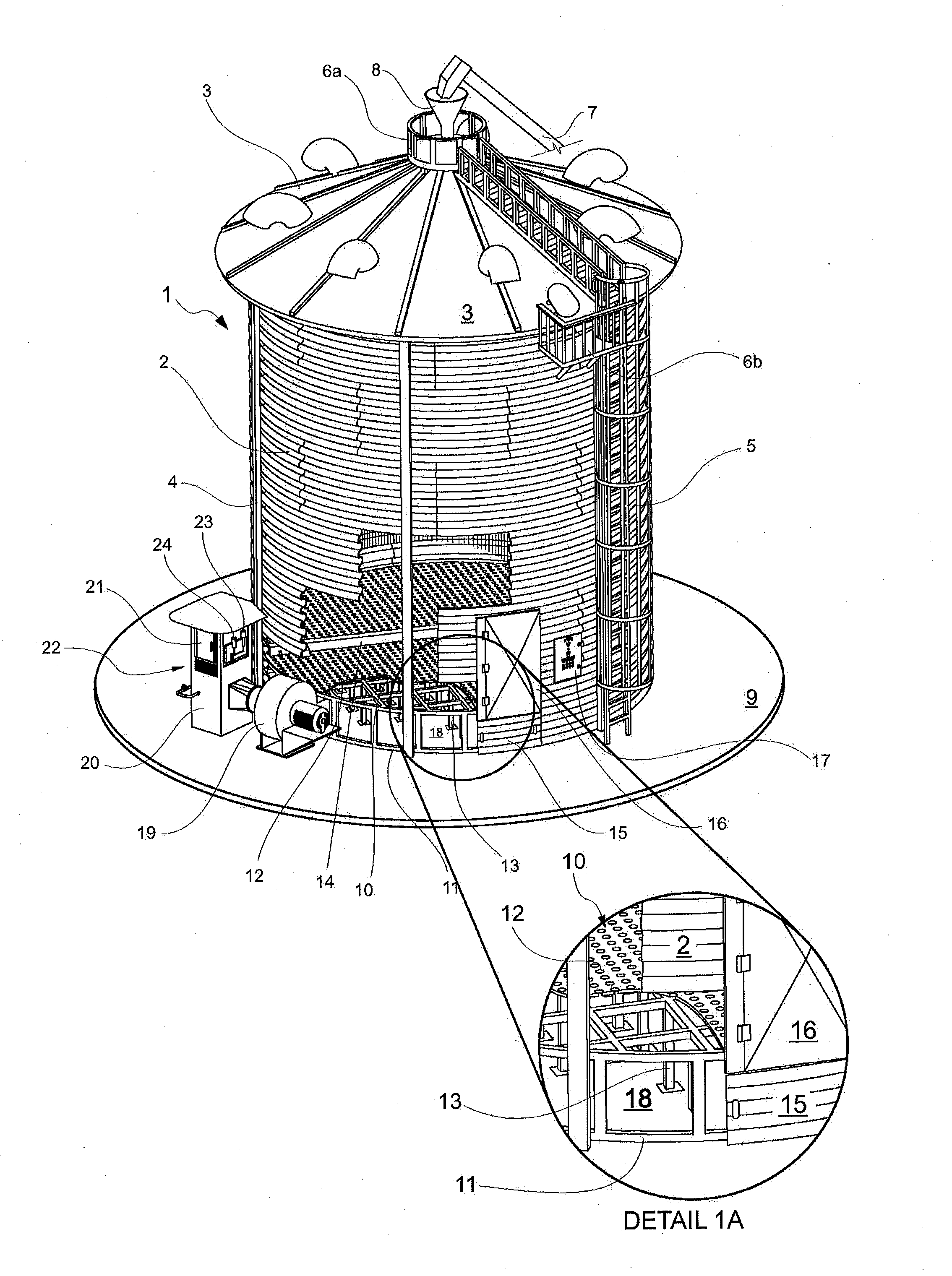
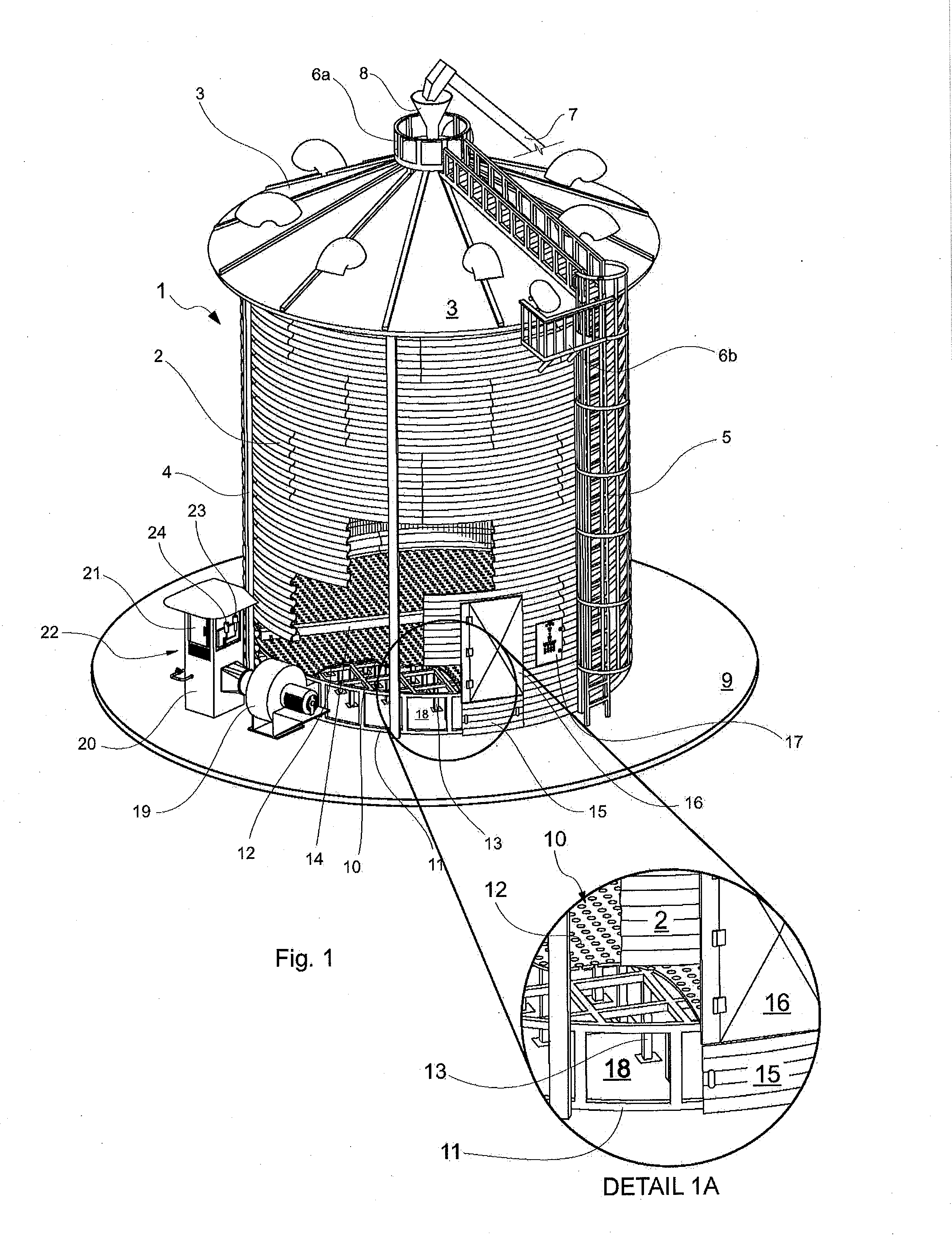
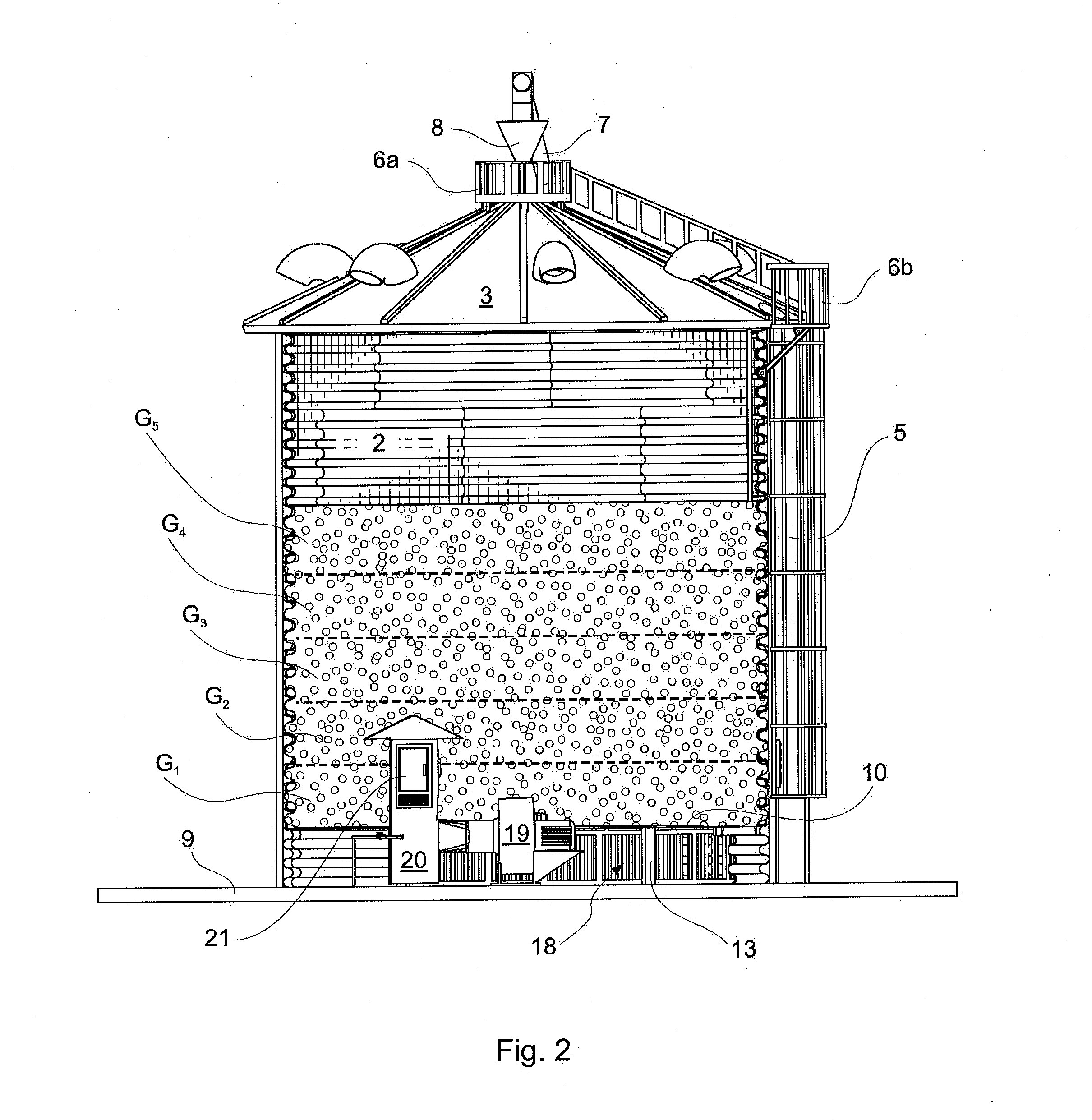
[0035]The grain humidity control facility according to a preferred example of an embodiment of the present invention has a general appearance as illustrated in FIG. 1, which distinguishes a silo (1) with a generally cylindrical shape preferably made of galvanized steel sheets (also known as zinc plates) shaped and bolted together so as to obtain the curved wall (2) laterally defining the grain storage enclosure; all of this being crowned at the top with a conical roof (3) also with zinc steel sheets. A plurality of rein...


PUM


Abstract

A facility for controlling the grain moisture provided with a grain storage silo conveniently installed on a hard flat floor and inside of which an elevated floor comprising air passageways is provided, determining an air chamber inside the silo and below the perforated floor, into which previously conditioned air is blown by an air heater, wherein the control of hot air blowing times is determined based on means of modeling and calculating on and off times applied through an electronic control means, with the ability to read and record manual input data entered by an operator and reading data from a temperature sensor in the air chamber, below the perforated floor, further aided with an ambient temperature and moisture sensor, thereby causing the application of different stages of drying, re-humidification and maintenance of the grain moisture.

Description

FIELD OF THE INVENTION[0001]The present invention relates to the field of devices, machines or apparatus for conditioning and moisture control of bulk materials, such as grains or seeds stored in silos; more specifically the present invention relates to a novel system for grain moisture control, capable of performing a novel predictive method for grain moisture control by means of an open loop control.BACKGROUND OF THE INVENTION[0002]In order to better understand the object and scope of the present invention, it is convenient to describe the closest known prior art regarding the use of facilities or silos for grain storing and drying, as well as the commonly used moisture control and temporary storage procedures of the harvested grain.[0003]In the present specification the terms “moisture” or “humidity” may be used interchangeably, but preferably the former is applied to solid products and the latter to gases, particularly air.[0004]In principle, the inventors of the present inventi...

Claims


Application Information

Patent Timeline
IPC IPC(8): A01F25/22F26B23/02F26B25/10F26B21/08
CPCA01F25/22F26B25/10F26B23/02F26B21/08F26B9/063F26B25/22F26B2200/06
Inventor BARTOSIK, RICARDODE LA TORRE, DIEGO
Owner INST NACIONAL DE TECNOLOGIA AGROPECUARIA
Learn More