
Total knee prosthesis, and set of modular elements making it possible to obtain such a prosthesis

Inactive Publication Date: 2014-12-04
AFRIAT JACQUES
View PDF0 Cites 9 Cited by
  • Summary
  • Abstract
  • Description
  • Claims
  • Application Information

AI Technical Summary

Benefits of technology

The present invention is about a knee prosthesis that solves problems associated with current design. It allows for optimal cooperation between the patent and femoral implants, while also reducing the risk of fibrous nodule formation at the junction of the quadricipital tendon and bony patella. The structure of the patella allows for transverse translation and tilting, which is ideal for optimal joint operation. The patellar implant is designed to limit the pivoting of the sliding element, and a femoral implant design is provided that includes an interlocking prominence that facilitates easy and quick positioning of an intercondylar cage on the femoral implant. This cage acts as a solid base for assembly of a medullary anchoring rod to the femur.

Problems solved by technology

In fact, without such resurfacing, the prosthetic joint would have abnormal kinematics and stress peaks, and the patient would be exposed to pain and abnormal rapid wear of the bony patella would occur.
Another drawback of the existing prostheses is the generation of a fibrous nodule at the junction of the quadricipital tendon and the bony patella (phenomenon known as “clunk syndrome”).

Method used


Image

  • Total knee prosthesis, and set of modular elements making it possible to obtain such a prosthesis
  • Total knee prosthesis, and set of modular elements making it possible to obtain such a prosthesis
  • Total knee prosthesis, and set of modular elements making it possible to obtain such a prosthesis

Examples


Embodiment Construction

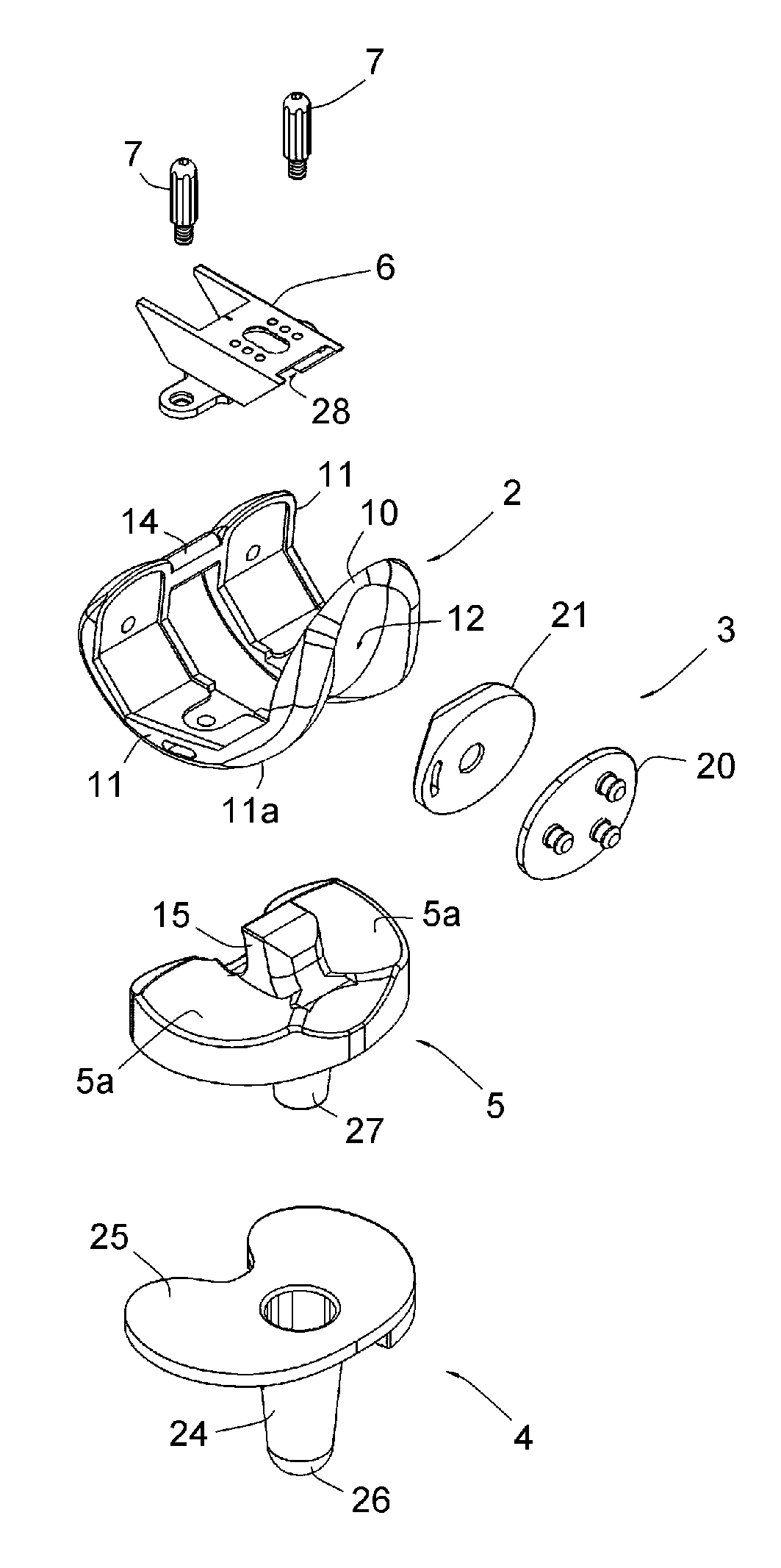
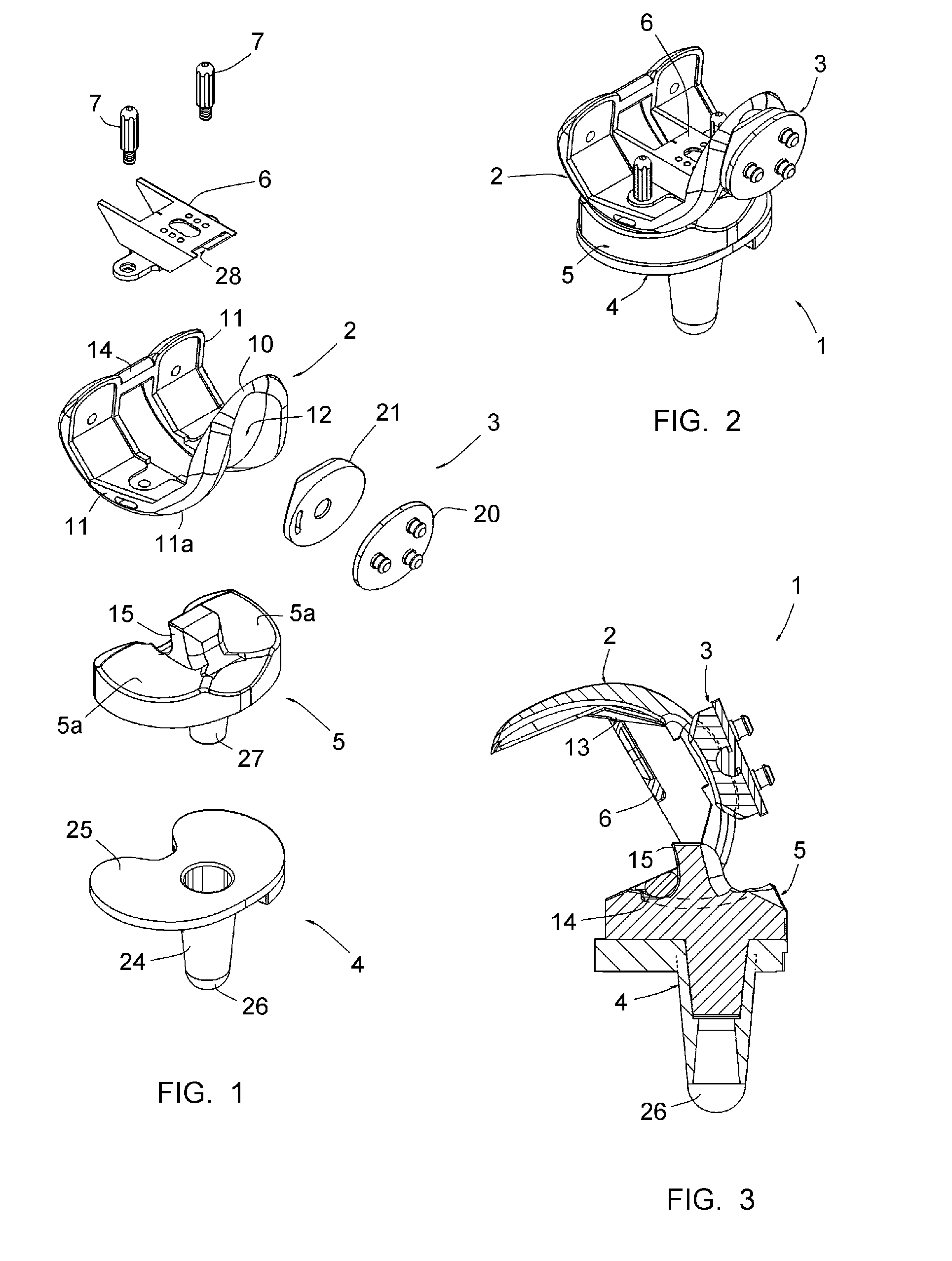
[0046]FIG. 1 shows a set of elements making it possible to obtain the posterior stabilized primary or initial prosthesis 1 shown in FIGS. 2 and 3.

[0047]This set of elements comprises a femoral implant 2, a patellar implant 3, a tibial implant 4, an intermediate sliding plate 5, an intercondylar cage 6 and two anchoring studs 7.

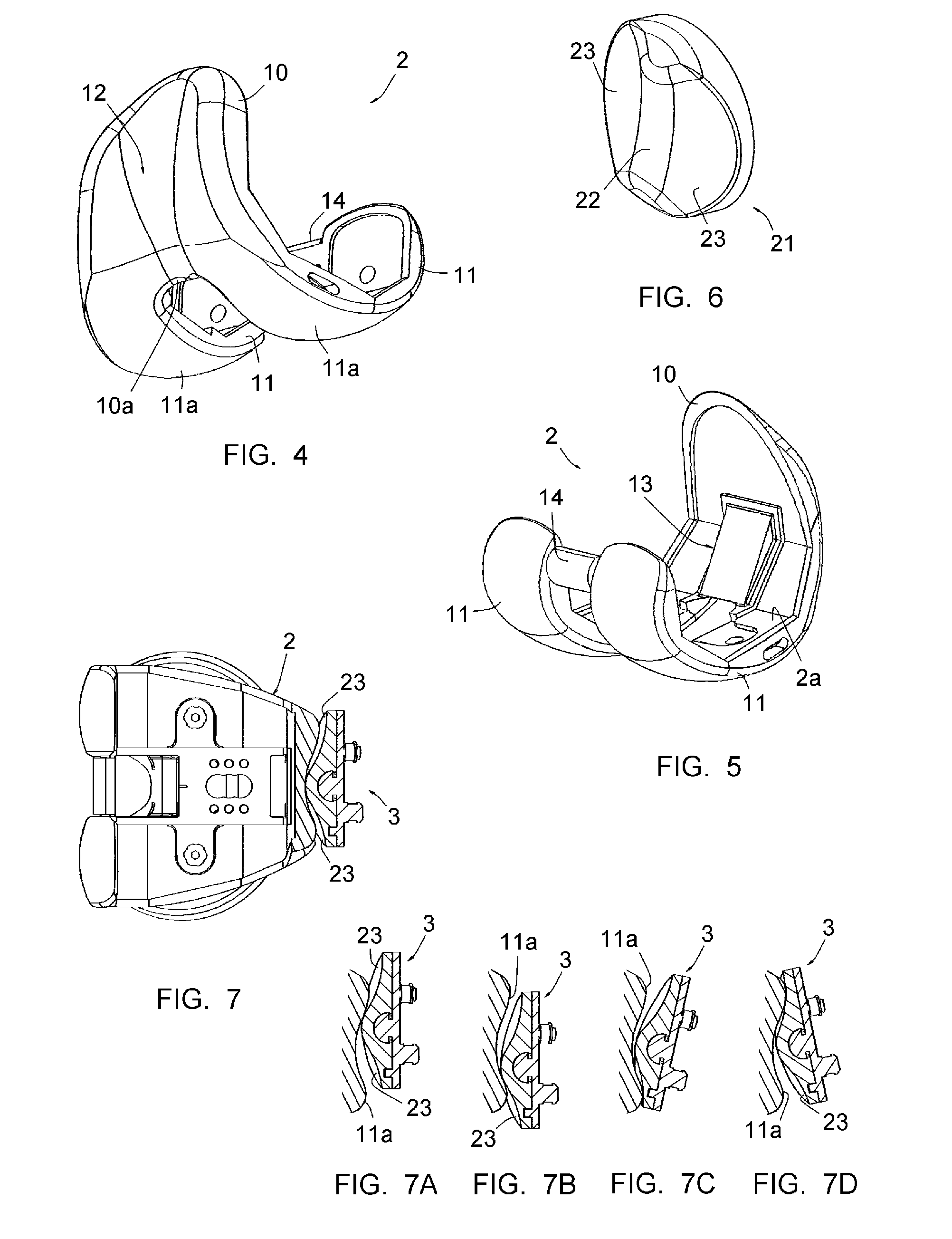
[0048]The femoral implant 2 is more particularly shown in FIGS. 4 and 5. It is formed by a single piece of metal having a curved shape capable of surrounding the lower end of a femur, resected accordingly. It comprises an anterior wall 10 and two curved branches 11 extending from the lower edge of said anterior wall 10.

[0049]On its outer side, the wall 10 forms the upper part of a prosthetic trochlea 12, the lower portion of which is delimited by the two branches 11 between them. The wall 10 thus has a lower edge 10a extending transversely to the branches 11; as more particularly shown in FIG. 4, and as will be understood in reference to FIGS. 9 and 10, the wa...


PUM


Abstract

The present invention concerns to a total knee prosthesis including a femoral implant having an anterior wall that forms the upper portion of a prosthetic trochlea and two curved branches extending from the lower edge of said anterior wall, delimiting the lower portion of the prosthetic trochlea between them and forming condylar surfaces between them. The trochlea has a middle furrow bordered by two rounded convex surfaces. The trochlea has in its upper portion a flexion of approximately 50°. The trochlea has a depth smaller than the height of the longitudinal middle rib comprised by the patella and has a width larger than that of that same rib, such that the patella comes into contact with the femoral implant essentially by that rib and said concave side faces are situated at a distance from said rounded convex surfaces. In the lower portion, the trochlea has a depth greater than the height of said rib and has a width substantially equal to that of said same rib, such that the patella comes into contact with the femoral implant essentially by said concave side faces, and said rib is at a distance from the bottom of the trochlea.

Description

TECHNICAL FIELD[0001]The present invention relates to a total knee prosthesis, and a set of modular elements making it possible to obtain said prosthesis.BACKGROUND OF THE INVENTION[0002]A total prosthesis of the knee traditionally comprises a femoral implant and a tibial implant made from metal, and an intermediate plate made from a material favoring sliding, in particular high-density polyethylene. Such a prosthesis also frequently comprises a patellar implant designed to be fastened on the bony patella after suitable resection thereof.[0003]The femoral implant has a curved shape capable of surrounding the lower end of a femur, resected accordingly; it comprises an anterior wall forming the upper part of a prosthetic trochlea, and two curved branches extending from the lower edge of said anterior wall, these two branches defining, between them, the lower part of the prosthetic trochlea and forming condylar surfaces.[0004]The tibial implant forms an upper wall for receiving said in...

Claims


Application Information

Patent Timeline
IPC IPC(8): A61F2/38
CPCA61F2/3859A61F2/3877A61F2/3886A61F2/389A61F2002/30331A61F2002/30332A61F2002/305A61F2002/30607A61F2002/30614A61F2002/30736A61F2002/30878
Inventor AFRIAT, JACQUES
Owner AFRIAT JACQUES
Learn More