Vibration isolation for superconducting magnets

a superconducting magnet and vibration isolation technology, applied in the field of superconducting magnets, can solve the problems of affecting the effect of magnetic field distortion, and affecting the effect of magnetic field distortion

Active Publication Date: 2014-12-04
SIEMENS HEALTHCARE GMBH
View PDF30 Cites 0 Cited by
  • Summary
  • Abstract
  • Description
  • Claims
  • Application Information

AI Technical Summary

Benefits of technology

[0009]An object the present invention addresses is to provide a rigid and stable mounting for the superconducting magnet when in use as part of an imaging system, while also providing effective isolation from shock loads during transportation.

Problems solved by technology

If the magnet were to be positioned even 1 mm away from its design position, the shielding would distort the magnetic field and degrade the images produced.
However, this is found unacceptable because the relatively fragile nature of the supporting structure of a typical superconducting magnet needs to be protected from shock loads experienced by the mobile carrier during transport.
An alternative is to make the supporting structure much stronger to withstand the shock loads, which will in turn lead to greater heat influx to the superconducting magnet, greater costs of cooling equipment or cooling cryogen materials.

Method used


Image

  • Vibration isolation for superconducting magnets
  • Vibration isolation for superconducting magnets
  • Vibration isolation for superconducting magnets

Examples


Embodiment Construction

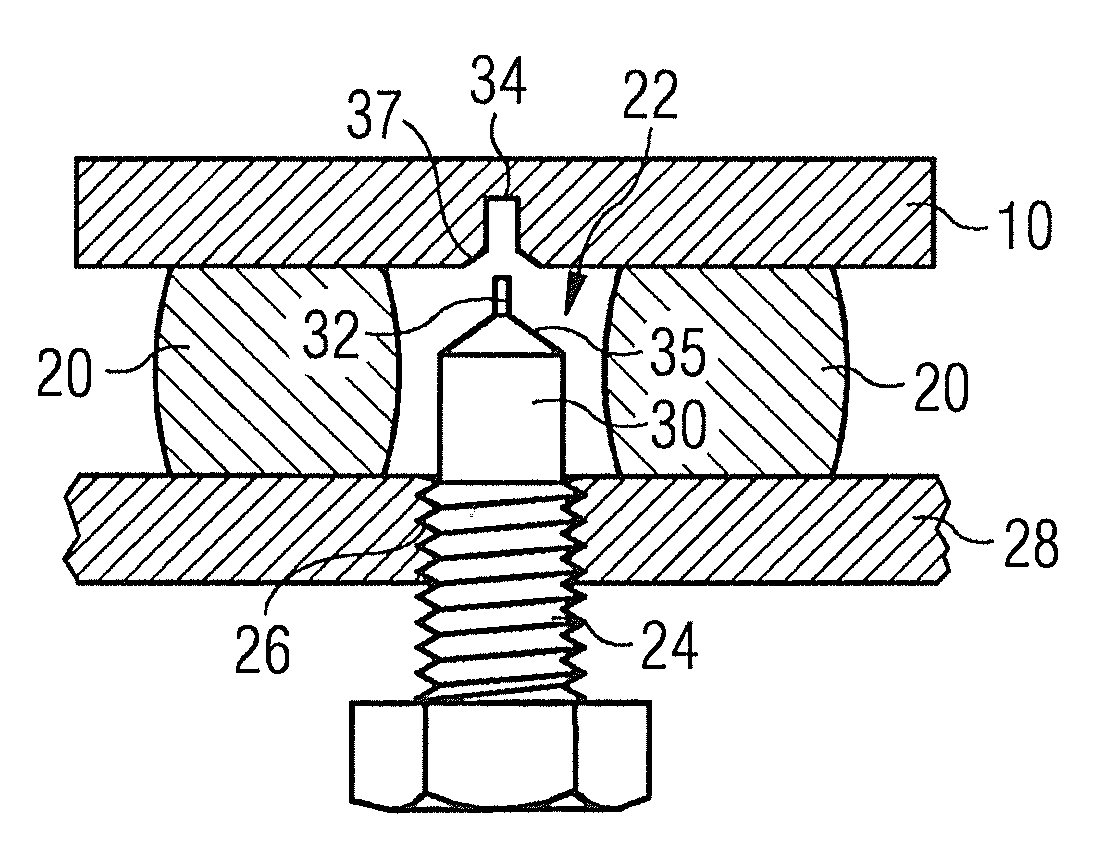
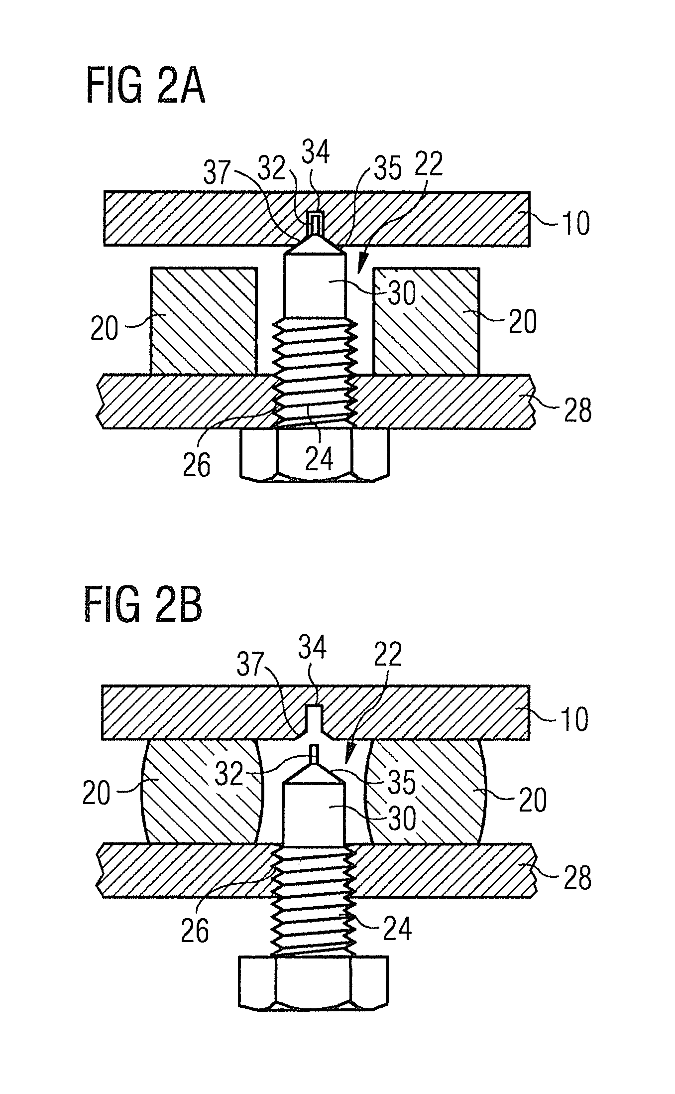
[0020]According to the present invention, mounting points are provided for locating under the superconducting magnet, between the magnet and a supporting surface of the mobile carrier. The mounting points of the present invention are controllable between two different states. In a first state, the mount provides rigid attachment and precise location of the superconducting magnet onto the supporting surface of the mobile carrier. In a second state, the mount provides vibration isolation between the superconducting magnet and the mobile carrier. Transition between the two states may be manually actuated, may be powered, or may be interlocked with systems of a tractor unit driving the mobile carrier. It is important that the magnet should return to exactly the same position each time that the mounting points are placed in their first state. This ensures that the shielding will have the same effect on the magnetic field in the imaging region each time, and so the homogeneity of the magn...


PUM

PropertyMeasurementUnit
travel distanceaaaaaaaaaa
superconductingaaaaaaaaaa
pressureaaaaaaaaaa

Abstract

A mounting plate for locating under a superconducting magnet structure, between the superconducting magnet structure and a supporting surface of a mobile carrier, is controllable between two different states. In a first state, the mount provides rigid attachment and precise location of the superconducting magnet structure onto the supporting surface of the mobile carrier. In a second state, the mount provides vibration isolation between the superconducting magnet and the mobile carrier.

Description

BACKGROUND OF THE INVENTION[0001]1. Field of the Invention[0002]The present invention relates to superconducting magnets which are transported and operated within a mobile carrier, such as a road trailer, railway carriage, or shipping container.[0003]2. Description of the Prior Art[0004]Superconducting magnets, particularly superconducting magnets used as part of a magnetic resonance imaging (MRI) or nuclear magnetic resonance (NMR) imaging system need to be held stably within their carrier, so that the magnet system is immobile during use as part of an imaging system.[0005]An example of such arrangements is the mobile MRI system, which may travel up to 500,000 miles (800,000 km) during its working life. The superconducting magnets of such systems are transported “at field”, that is to say, having electric current flowing in the superconducting magnet and generating a magnetic field. The typical use for such a system is to provide an imaging facility in a town which does not otherwi...

Claims


Application Information

Patent Timeline
Patent Type & Authority Applications(United States)
IPC IPC(8): G01R33/385G01R33/3815H01F6/00
CPCG01R33/3854G01R33/3815H01F6/00G01R33/3802F16F15/043F16F15/06F16F15/08
Inventor BELTON, NEILGOWLAND, RICHARDHUSBAND, TREVOR BRYANMANN, NICHOLASSIMPKINS, MICHAEL
Owner SIEMENS HEALTHCARE GMBH
Why Eureka
Try Eureka