Folded expansion bolt

A technology of expansion bolts and bolts, applied in the direction of connecting components, pins, mechanical equipment, etc., can solve the problems of low bearing capacity, easy loosening of stone plates, and troublesome disassembly.

Pending Publication Date: 2015-04-08
伍振成
View PDF11 Cites 0 Cited by
  • Summary
  • Abstract
  • Description
  • Claims
  • Application Information

AI Technical Summary

Problems solved by technology

Existing expansion bolts are composed of bolts, nuts, and expansion sleeves. The bolts have tapered ends, and one end of the expansion sleeve is provided with a narrow slot. Drive the screw into the installation hole, then put the equipment installation hole on the threaded end of the head of the drop rod, and finally screw the nut on the threaded end of the head of the tie rod to fix the device on the wall. During the process of tightening the nut, the screw goes out While the expansion tube does not move, the frustum-shaped expansion tube at the screw rod tail expands to make it swell to fill the entire hole, thereby achieving fixation; the expansion bolt in the prior art has errors in the diameter of the hole punched on the stone plate, and the nut The expansion tube of the expansion bolt cannot be completely expanded due to different tightening degrees, etc. At the same time, due to the small contact surface with the installation hole, the stone plate installed on the pendant is easy to loosen, and the structure is weak. The reason is that it is troublesome to disassemble and cannot be recycled; and the carrying capacity is not large

Method used


Image

  • Folded expansion bolt
  • Folded expansion bolt
  • Folded expansion bolt

Examples


Embodiment 1

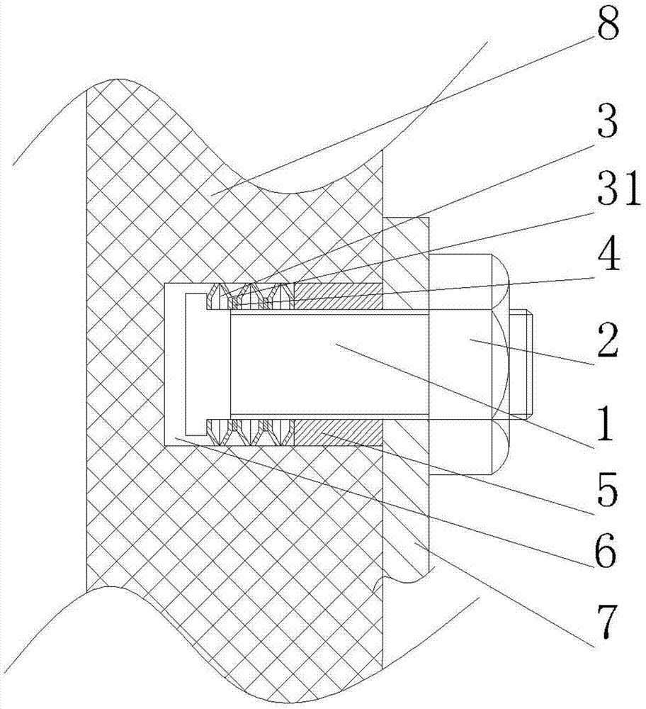
[0013] Such as figure 1 , figure 2 , image 3 As shown, a stacked expansion bolt includes a T-shaped bolt 1, a nut 2 set on the T-shaped bolt 1, several pairs of stacked frustum-cone expansion sleeves 3 set on the T-shaped bolt 2, Sleeve 4 on the outside of stacked frustum expansion sleeve 3 . When in use, press the overlapping expansion bolts into the mounting holes, the outer end of the T-bolt 1 passes through the pendant 7, and then screw on the nut 2, the T-bolt 1 goes outward, and the overlapping expansion bolts are connected between the T-bolt 1 and the sleeve. Expand under the action of the cylinder 4 to make it fill the entire hole, fix the pendant 7 on the wall 8, and then fix the stone plate 4 on the pendant 7.

Embodiment 2

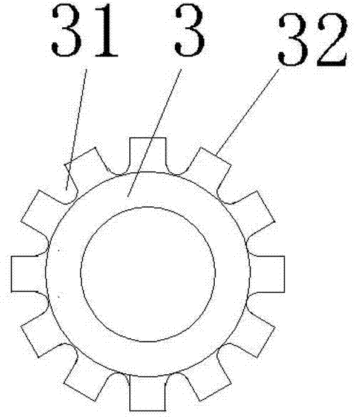
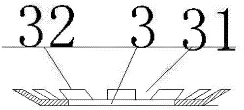
[0015] Such as figure 1 , figure 2 , image 3 As shown, the overlapping frustum expansion sleeve 3 is formed by overlapping the lower bottoms of two frustum expansion sleeves 31. A spacer ring 5 is provided between the overlapping expansion sleeves 3 to prevent adjacent The frustum expansion sleeves 31 fit together to reduce the bending force when the frustum expansion sleeves 31 are installed, and facilitate the entry of the frustum expansion sleeves 31 into the installation hole 6. The outer surface of the sleeve 4 and the lower bottom of the frustum expansion sleeve 31 The diameters are equal, and the sleeve 4 is used to press the stacked frustum-cone expansion sleeve 3 into the installation hole 6 during installation. The upper bottom of the frustum-cone expansion sleeve 31 is equal to the outer diameter of the spacer ring 5 . The lower bottom of the frustoconical expansion sleeve 31 is provided with several notches 32 to form several openings 33 .


PUM


Abstract

The invention relates to the field of bolts, in particular to a folded expansion bolt. The folded expansion bolt comprises a T-shaped bolt, a nut, a plurality of pairs of folded frustum expansion bushings and sleeves, wherein the nut is arranged on the T-shaped bot; the folded frustum expansion bushings sleeve the T-shaped bolt; the sleeves are arranged on the outer sides of the folded frustum expansion bushings. Since the structure is arranged, the expansion bolt is detachable, and can be repeatedly used and can be placed in a mounting hole in an unobstructed manner, the mounting and fastening force is high and stable, the use cost is low, the mounting is facilitated, and the expansion bolt can be used for mounting and fixation of stone slabs.

Description

technical field [0001] The invention relates to the field of bolts, in particular to an overlapping expansion bolt. Background technique [0002] Expansion bolts are used to fix objects on walls or boards. The principle is to use the wedge-shaped slope to promote expansion and achieve a fixed effect. Existing expansion bolts are composed of bolts, nuts, and expansion sleeves. The bolts have tapered ends, and one end of the expansion sleeve is provided with a narrow slot. Drive the screw into the installation hole, then put the equipment installation hole on the threaded end of the head of the drop rod, and finally screw the nut on the threaded end of the head of the tie rod to fix the device on the wall. During the process of tightening the nut, the screw goes out While the expansion tube does not move, the frustum-shaped expansion tube at the screw rod tail expands to make it swell to fill the entire hole, thereby achieving fixation; the expansion bolt in the prior art h...

Claims


Application Information

Patent Timeline
IPC IPC(8): F16B13/06
CPCF16B13/063
Inventor 伍振成
Owner 伍振成
Why Eureka
Try Eureka