Airlift pump with helical flow pattern

a flow pattern and airlift pump technology, applied in the direction of machines/engines, machine/engines, and removal of fluids, can solve the problems that airlift pumps by nature cannot achieve the efficiency or the lifting height of motorized mechanical pumps, and achieve the effect of enhancing the entrainment of more fluid through the device, reducing pressure, and increasing efficiency

Inactive Publication Date: 2014-12-04
KING FAHD UNIVERSITY OF PETROLEUM AND MINERALS
View PDF9 Cites 2 Cited by
  • Summary
  • Abstract
  • Description
  • Claims
  • Application Information

AI Technical Summary

Benefits of technology

[0007]The airlift pump with helical flow pattern includes a nozzle body defining a central fluid passage and having a plurality of helically inclined air injection nozzles surrounding the central passage. The laterally outward side of each of the injector nozzle passages is tangent to the inner wall or surface of the central fluid passage of the nozzle body. Air (or other gas) injected into the central fluid passage produces a circumferential flow. Each of the injector nozzle passages is also inclined in the general direction of fluid flow through the body. The tangential and sloping orientation of the air injection passages results in a helical flow pattern for the air or gas injected into the nozzle body. This helical flow pattern imparts a similar flow pattern to the fluid passing through the nozzle body. The rotating flow results in a decrease in pressure through the center of the flow due to the centrifugal effect of the rotating fluid flow. This pressure drop enhances the entrainment of more fluid through the device, thereby increasing its efficiency.
[0008]The tangential orientation of the air or gas injection nozzles results in a completely open fluid flow passage through the nozzle body, thereby further increasing the efficiency of the device by removing any structure that would otherwise produce hydrodynamic resistance to flow through the body. The entrance to the fluid flow passage is also smoothly radiused in order to reduce turbulent flow at this point. A riser or standpipe is attached to the upper or outlet end of the nozzle body. The riser preferably has the same internal diameter as the fluid passage of the nozzle body. The fluid passages of both the nozzle body and the riser preferably have uniform internal diameters to maximize smooth flow through the apparatus. The riser or standpipe is preferably sealed to the upper end of the nozzle body to preclude leakage and flow disruption at that point, e.g., by an O-ring or other suitable sealing means.

Problems solved by technology

However, airlift pumps by their nature cannot achieve the efficiency or the lifting height of motorized mechanical pumps.

Method used


Image

  • Airlift pump with helical flow pattern
  • Airlift pump with helical flow pattern
  • Airlift pump with helical flow pattern

Examples


Embodiment Construction

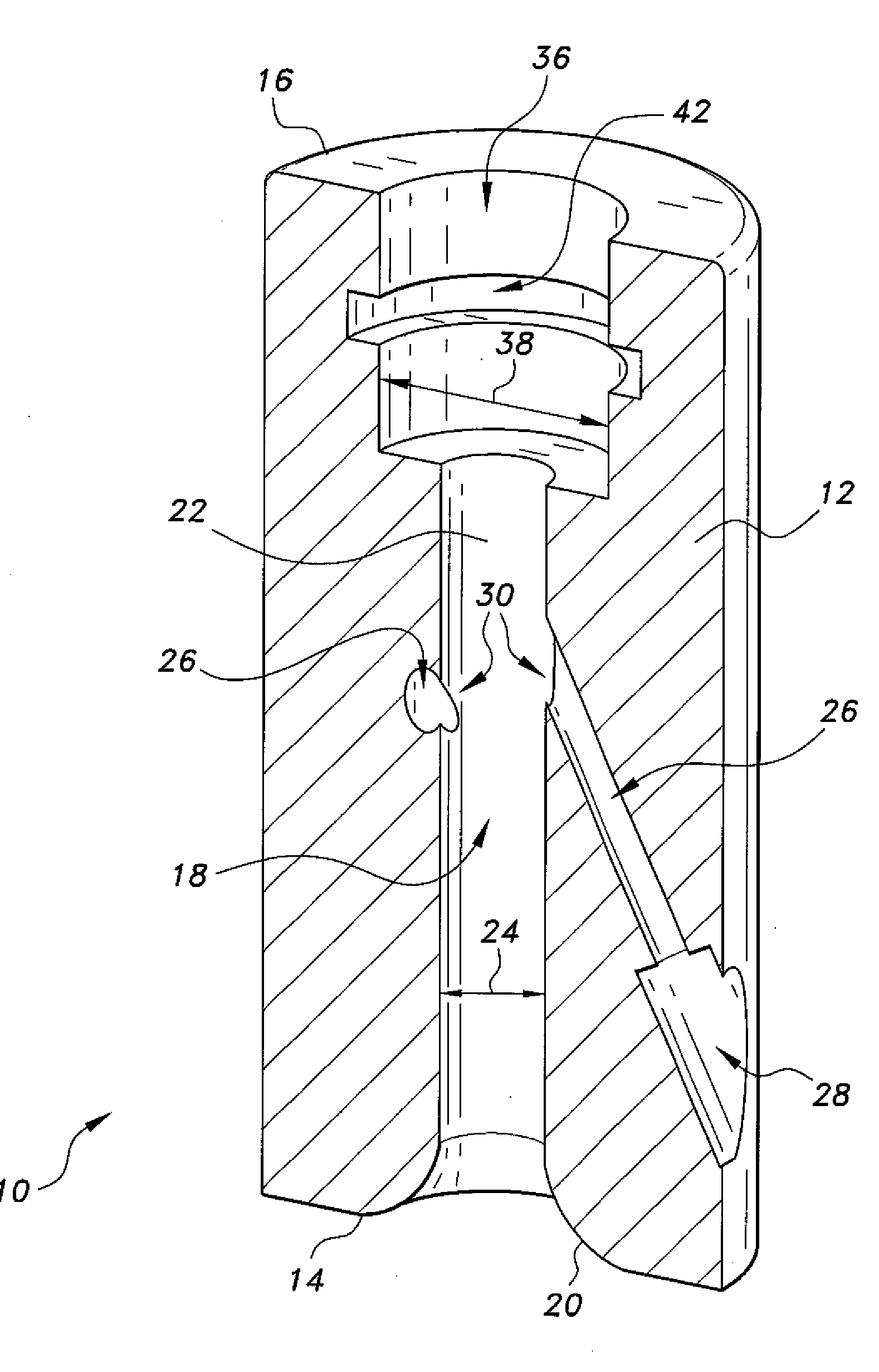
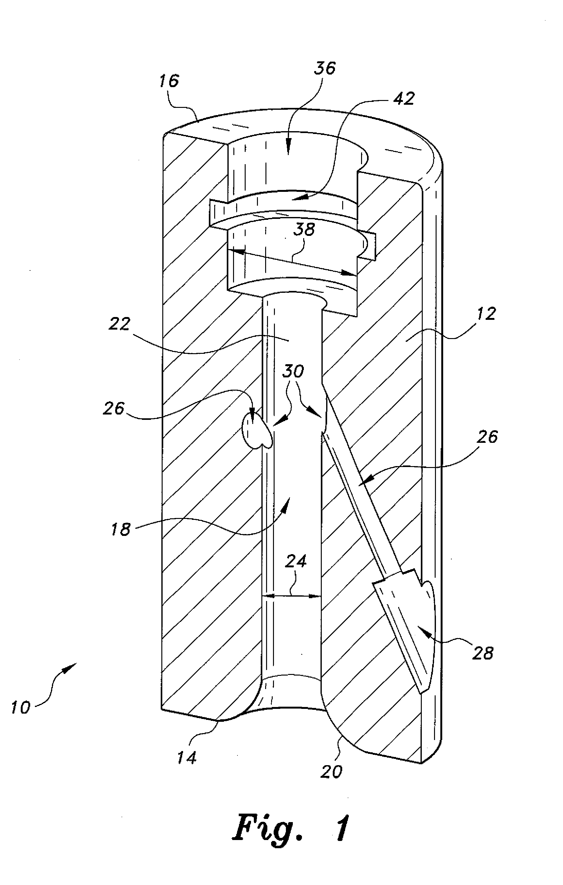
[0016]The airlift pump having a helical flow pattern includes a plurality of air or gas injection nozzles disposed tangentially to the wall of the central passage and inclined toward the upper or outlet end of the passage to impart a helical flow to liquid entrained in the device. This helical flow pattern imparts additional energy to the liquid flow through the device in comparison to conventional flow patterns, thereby increasing the lift height of the liquid pumped through the device.

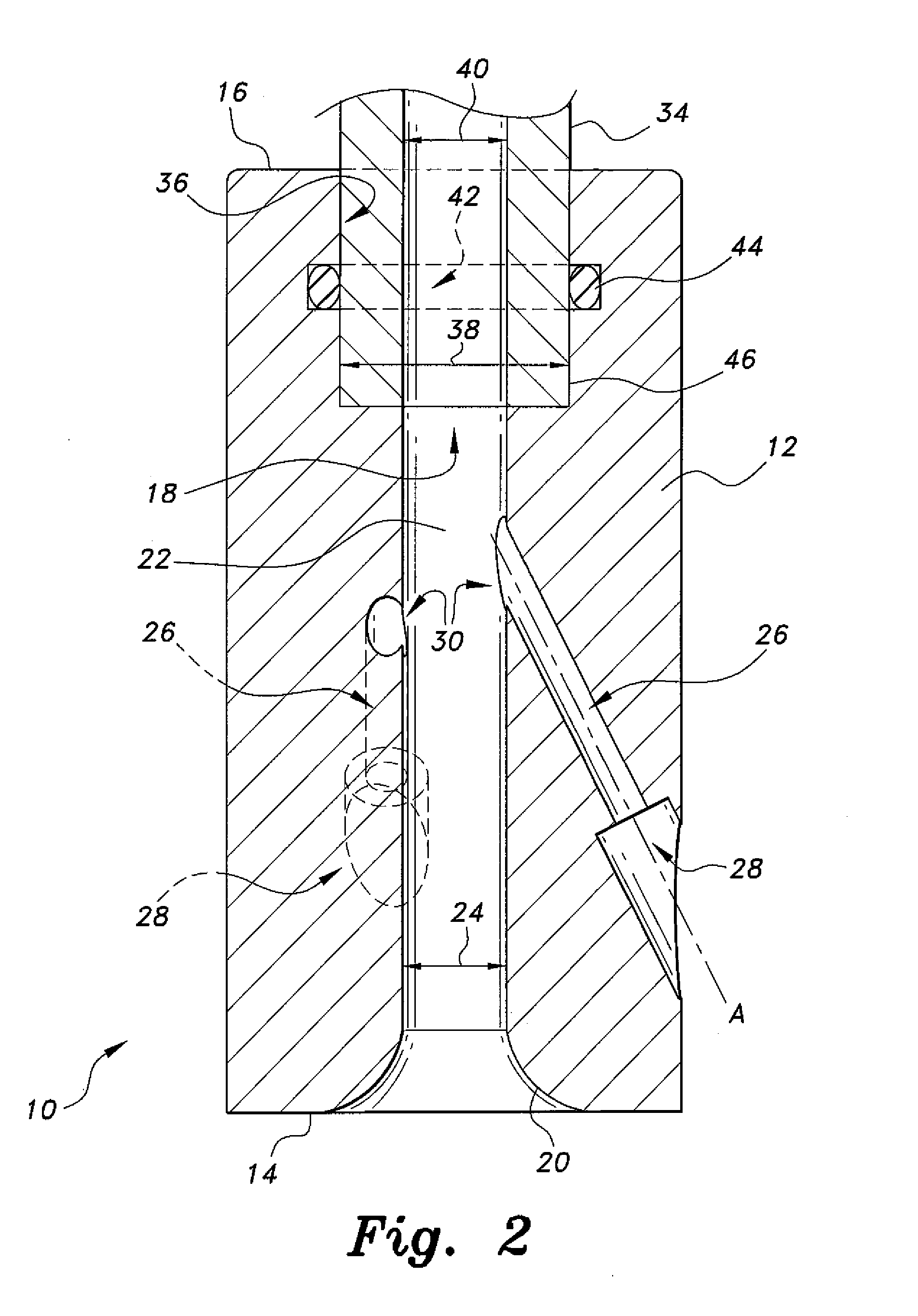
[0017]FIG. 1 of the drawings provides a perspective view in section of the airlift pump with helical flow pattern, designated generally as 10 in the drawings. FIG. 2 provides an additional elevation view in section of the airlift pump 10 that also shows the attachment of a riser pipe to the upper end of the device. The airlift pump 10 comprises a nozzle body 12 having a lower inlet end 14 and an opposite upper outlet end 16. A fluid flow passage 18 is disposed concentrically within the nozzle body 12...


PUM


Abstract

The airlift pump with helical flow pattern includes a nozzle body having a fluid passage therethrough. A plurality of air or gas injector nozzles surrounds the central passage. The outward side of each nozzle is tangent to the fluid passage wall through the body to produce circumferential flow in the fluid passage. Each of the air injector nozzles is also inclined in the direction of flow through the body, the tangential inclination resulting in a helical flow pattern through the body. The centrifugal force generated by the circumferential and helical flow through the body results in a pressure decrease through the core of the fluid passage, thereby enhancing entrainment of fluid into the device to increase its efficiency. The fluid passage through the nozzle body is devoid of any structure, and the inlet end of the passage is smoothly radiused to further increase the efficiency of the device.

Description

BACKGROUND OF THE INVENTION[0001]1. Field of the Invention[0002]The present invention relates generally to fluid pump devices, and particularly to an airlift pump with helical flow pattern that has a plurality of helically oriented air injection nozzles for imparting an upward helical flow pattern to the entrained fluid being drawn through the pump.[0003]2. Description of the Related Art[0004]The conventional airlift pump is a simple device, comprising a discharge or jet of air or other gas into the lower end or portion of a substantially vertical standpipe situated in a body of water or other liquid. The air or gas jet entrains the liquid and lifts the liquid within the pipe to expel the liquid from the open top of the pipe, or from a discharge pipe or tube extending from the top of the pipe. Relatively small solid particulates (e.g., sand and gravel) may also be lifted from the bottom of the body of water, depending upon the energy in the airstream and other factors.[0005]Airlift ...

Claims


Application Information

Patent Timeline
Patent Type & Authority Applications(United States)
IPC IPC(8): F04F5/00
CPCF04F5/00F04F1/18
Inventor AHMED, WAEL HASANBADR, HASSAN MOHAMEDAL-QUTUB, AMRO MOHAMED
Owner KING FAHD UNIVERSITY OF PETROLEUM AND MINERALS
Why Eureka
Try Eureka