
Shielded Audio Apparatus

a shielding and audio technology, applied in the direction of loudspeaker screens, transducer details, microphone structural associations, etc., can solve the problems of reducing the performance of these components, damage to sensitive components, and component damag

Active Publication Date: 2014-12-04
NOKIA TECHNOLOGLES OY
View PDF12 Cites 12 Cited by
  • Summary
  • Abstract
  • Description
  • Claims
  • Application Information

AI Technical Summary

Benefits of technology

The patent describes an apparatus for generating sound waves using a transducer membrane and a plate. The plate is designed to produce a magnetically shielded region to prevent particles from reaching the transducer membrane. The apparatus also includes a cover with a conduit for sound waves to pass through. The cover may have a coating to lower its permeability. The apparatus may also have a support for the transducer and an audio driver. The technical effects of the invention include improved sound wave generation and protection of the transducer from damage.

Problems solved by technology

However dust and other small particles (and water) can often reach the transducer components and cause component damage.
These particles can damage the sensitive components and / or reduce the performance of these components when the apparatus is in operation.
For example after some time the force between magnetic dust on the diaphragm and the permanent magnet inside the electrodynamic loudspeaker can pull the diaphragm towards the magnet and make the sound quieter, cause distortion or both.
These types of failure typically requires repair and are costly to the manufacturer of the device if the failure occurs within the warranty period.
Furthermore these features can cause brand damage if the failure occurs soon after the warranty period as the user considers the device to have failed prematurely and of poor quality.

Method used


Image

  • Shielded Audio Apparatus
  • Shielded Audio Apparatus
  • Shielded Audio Apparatus

Examples


Embodiment Construction

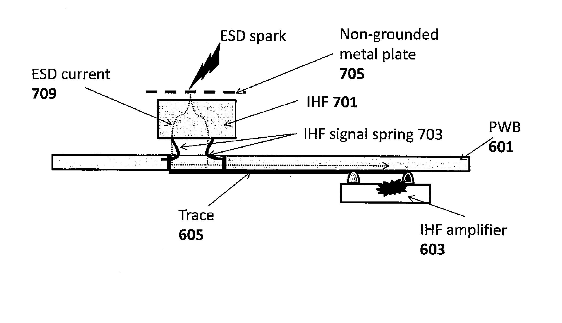
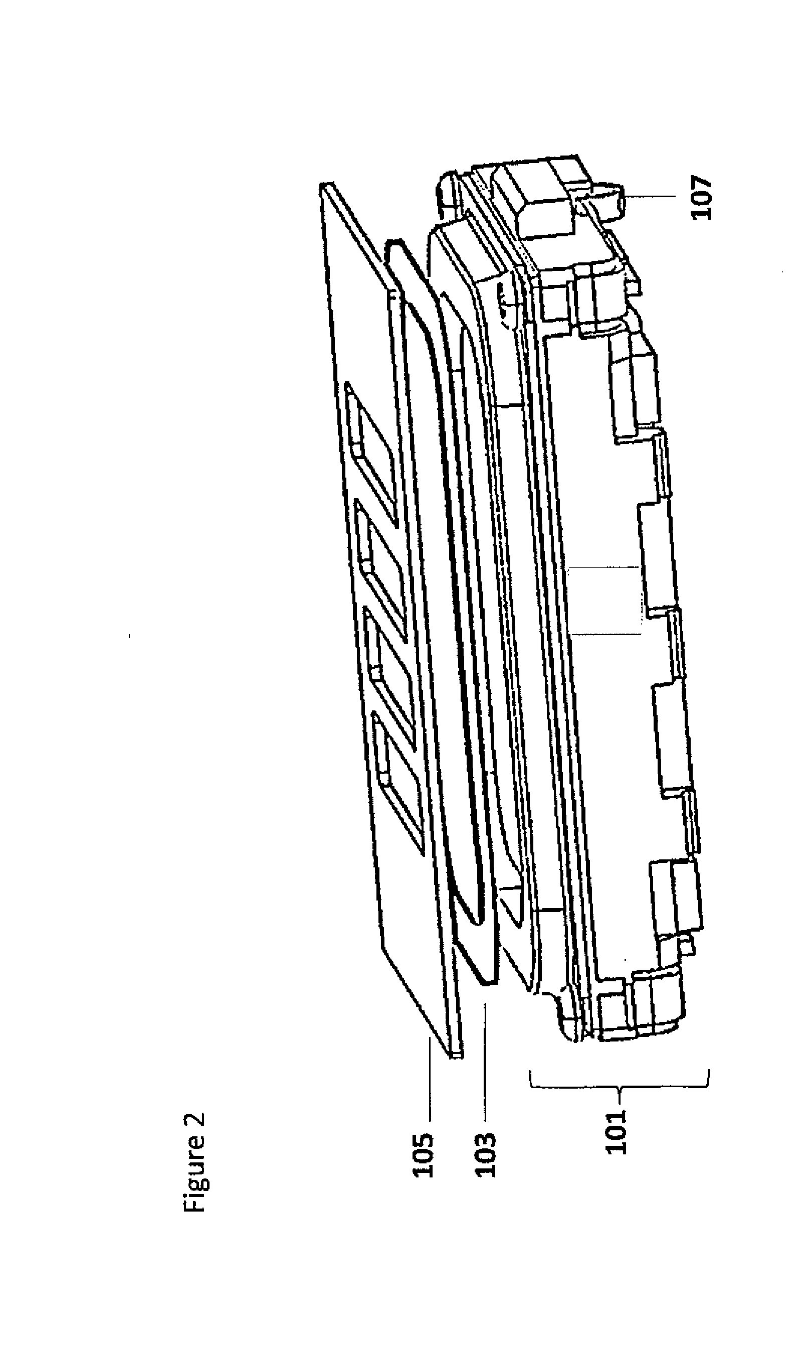
[0005]In a first aspect of the application there is provided an apparatus comprising a transducer membrane for generating sound waves: and a plate, through which sound waves can pass, at least partially overlaying the transducer membrane configured to produce a magnetically shielded region to impede particles reaching the transducer membrane.

[0006]The plate may be located between the transducer membrane and an apparatus cover with at least one conduit configured to permit sound waves to pass through the at least one plate.

[0007]The apparatus may further comprise a dust net located proximate to the at least one conduit configured to permit sound waves to pass through the dust net.

[0008]The apparatus may further comprise a cover comprising at least one cover conduit configured to permit sound waves to pass through the cover.

[0009]The at least one cover conduit and the plate conduit may be skewed with respect to the relative direction to the transducer membrane.

[0010]The plate conduit ...


PUM


Abstract

An apparatus including a transducer membrane for generating sound waves; and a plate, through which sound waves can pass, at least partially overlaying the transducer membrane configured to produce a magnetically shielded region so to impede particles reaching the transducer membrane.

Description

FIELD OF THE APPLICATION[0001]The present application relates to a method and apparatus for magnetic and electrostatic discharge shielding. In some embodiments the method and apparatus relate to a magnetic and electrostatic discharge shielding for transducers.BACKGROUND OF THE APPLICATION[0002]Some portable electronic devices comprise transducers such as loudspeakers and / or earpieces which are required to be small in size. Transducers are important components in electronic devices such as mobile phones for the purposes of playing back music or having a telephone conversation. The quality and loudness of a transducer in an electronic device are important especially if a user listens to sounds generated by an electronic device at a distance from the electronic device.[0003]Furthermore in portable devices dust and water protection is important specifically with regards to the transducers. However dust and other small particles (and water) can often reach the transducer components and c...

Claims


Application Information

Patent Timeline
IPC IPC(8): H04R1/02
CPCH04R1/02H04R3/007H04R1/04H04R1/023H04R2209/022H04R1/06
Inventor TOSSAVAINEN, ANTERO JOHANNESKAJANUS, VEIJOGUO, JIAN
Owner NOKIA TECHNOLOGLES OY
Learn More