Bellows synthetic jet

a synthetic jet and belt technology, applied in the direction of positive displacement liquid engines, air-flow influencers, machines/engines, etc., can solve the problem that the fireplace bellows doesn't generate a synthetic jet, and achieve the effect of more fluid motion through the aperture and improving the efficiency of the devi

Active Publication Date: 2014-11-27
THE BOEING CO
View PDF7 Cites 5 Cited by
  • Summary
  • Abstract
  • Description
  • Claims
  • Application Information

AI Technical Summary

Benefits of technology

The patent describes a device that uses flapping motion to create a pressure distribution that increases from the front to the back of a chamber. The device has a flap that is hinged, allowing it to move in parts of the chamber that have the greatest pressure. The flap is shaped in a way that causes a funneling effect, which increases the efficiency of the device. The device also has flexible sidewalls that move as the flaps move, which improves its efficiency and allows more fluid motion through an aperture compared to a device with rigid sidewalls.

Problems solved by technology

Although, a fireplace bellows doesn't generate a synthetic jet.

Method used


Image

  • Bellows synthetic jet
  • Bellows synthetic jet
  • Bellows synthetic jet

Examples


Embodiment Construction

[0025]In the following description, numerous specific details are set forth in order to provide a thorough understanding of the presented concepts. The presented concepts may be practiced without some or all of these specific details. In other instances, well known process operations have not been described in detail so as to not unnecessarily obscure the described concepts. While some concepts will be described in conjunction with the specific embodiments, it will be understood that these embodiments are not intended to be limiting.

INTRODUCTION

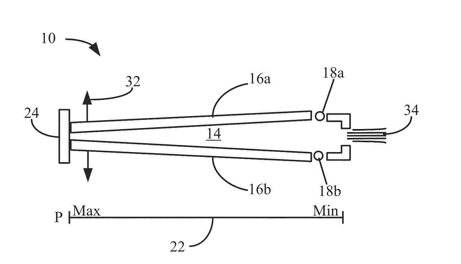
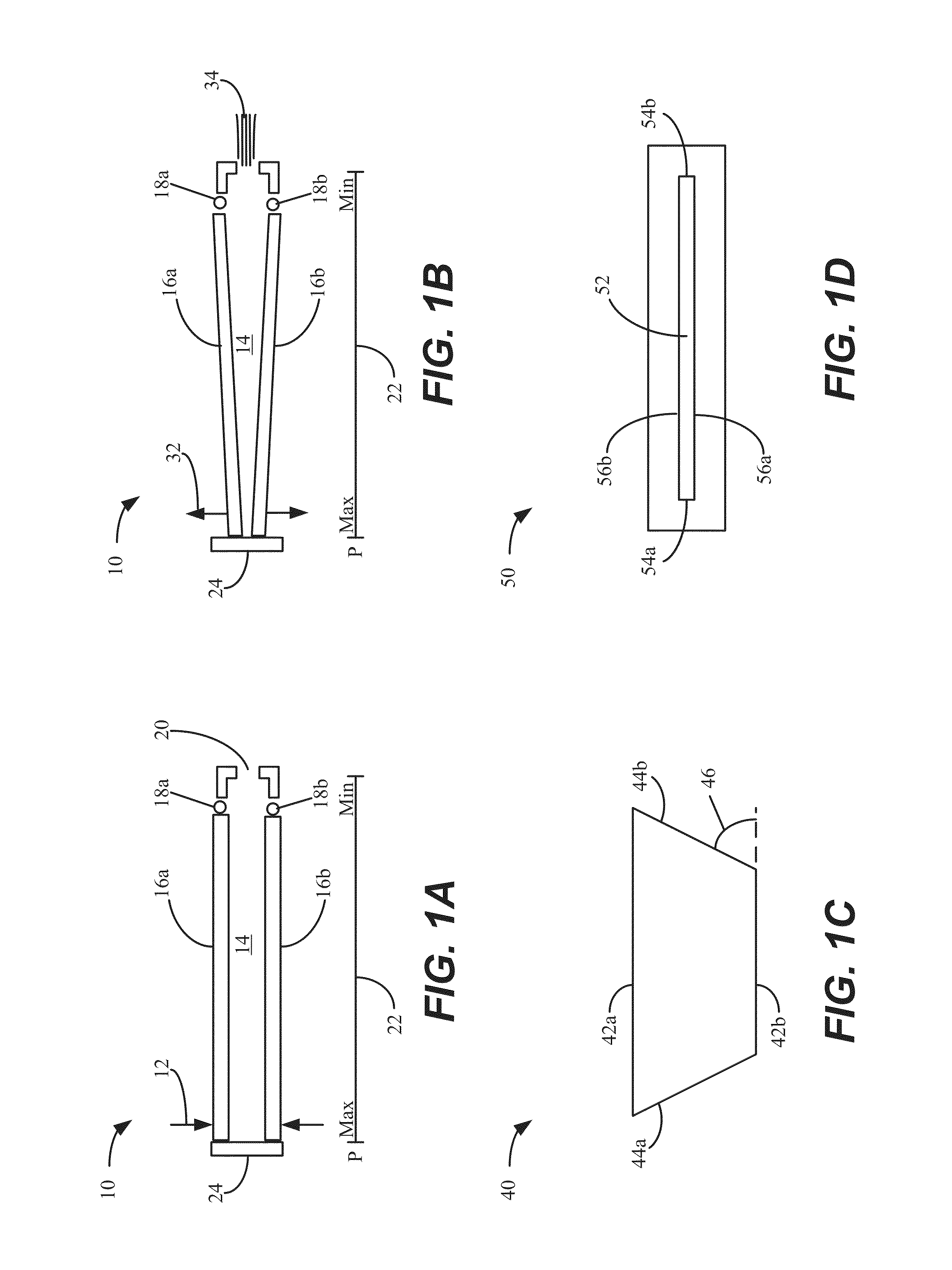
[0026]A mechanism for generating a synthetic jet is described. In particular embodiments, an actuator is used to move a hinged flap or multiple actuators are used to move multiple flaps. The flaps act on a fluid within a cavity formed using the flaps. The motion which is generated is similar to the motion associated with a fireplace bellows. Although, a fireplace bellows doesn't generate a synthetic jet. Thus, the mechanism can be referred to...


PUM


Abstract

A device for generating a synthetic jet is described. The device can include a flap, an actuator coupled to the flap and a chamber including an aperture. The flap forms a portion of the chamber. The flap is configured to oscillate in a flapping motion such that fluid is alternately drawn into the chamber via the aperture and expelled from the chamber via the aperture to form the synthetic jet. In some embodiments, multiple flaps can be used on a device to generate the synthetic jet.

Description

BACKGROUND[0001]A synthetic jet is generated by alternating momentary ejection and suction of a fluid across an orifice such that the net mass flux is zero. A typical configuration for a device used to generate a synthetic jet is to place a biomorph piezoelectric disk at the bottom of a cylinder. The cylinder includes a small orifice opposite the piezoelectric disk. The effect of the bending disk is to actuate like a piston head to generate ejection and suction through the orifice. In response to the motions, vortices are generated which propagate away from the orifice. The synthetic jet is formed when the vortices generated by the orifice coalesce to form a jet, in a time-averaged sense.[0002]A synthetic jet actuator can be deployed in a flow control system. A unique feature of synthetic jets is that they are formed entirely from the working fluid of the flow system. Thus, the jets can be used to transfer linear momentum to the flow system without a net injection of mass.[0003]Synt...

Claims


Application Information

Patent Timeline
Patent Type & Authority Applications(United States)
IPC IPC(8): F04B43/00
CPCF04B43/00F15D1/0095B64C21/025B64C21/08B64C2230/18Y02T50/10
Inventor GRIFFIN, STEVENWHALEN, EDWARD A.HAAR, SHAWN
Owner THE BOEING CO
Why Eureka
Try Eureka