
Motor and method of manufacturing motor

a manufacturing method and motor technology, applied in the direction of manufacturing stator/rotor bodies, magnetic circuit shapes/forms/construction, solid insulation, etc., can solve the problems of increased magnetic reluctance in each folding portion including the cut, and increased magnetic reluctance in the folding portion. to achieve the effect of reducing the increase in magnetic reluctance of the cor

Inactive Publication Date: 2014-11-27
NIPPON DENSAN CORP
View PDF4 Cites 9 Cited by
  • Summary
  • Abstract
  • Description
  • Claims
  • Application Information

AI Technical Summary

Benefits of technology

This patent is about a way to make motors that have less resistance to the magnetic field. This is important because it helps the motor work better. The invention involves bending a straight piece of metal into a protective shape, which reduces the area around the cut where the magnetic field is affected. This results in a motor that is more efficient.

Problems solved by technology

The aforementioned structure described in JP-A H11-069738 has a problem in that magnetic reluctance is increased in each folding portion including the cut.
This opening causes an additional increase in the magnetic reluctance in the folding portion.
As a result, magnetic flux may be disturbed between the adjacent teeth.

Method used


Image

  • Motor and method of manufacturing motor
  • Motor and method of manufacturing motor
  • Motor and method of manufacturing motor

Examples


Embodiment Construction

[0018]Hereinafter, preferred embodiments of the present invention will be described with reference to the accompanying drawings.

General Preferred Embodiment

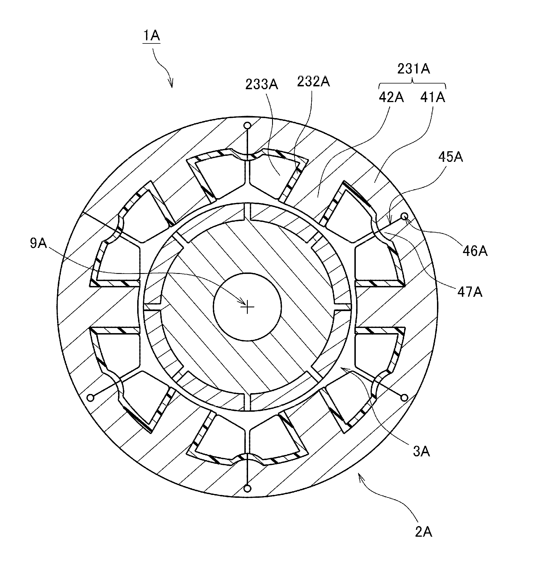
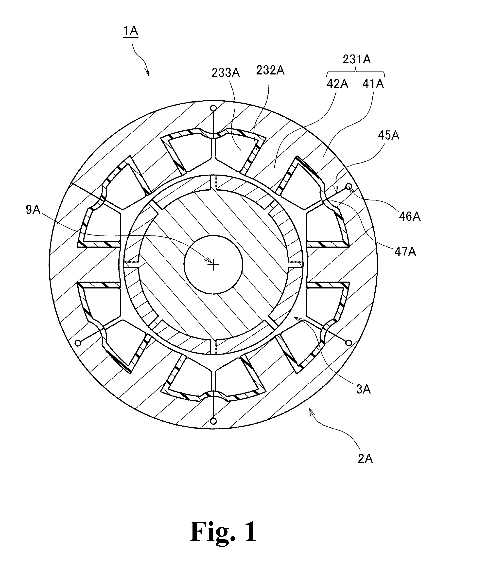
[0019]FIG. 1 is a horizontal cross-sectional view of a motor 1A according to a preferred embodiment of the present invention taken along a plane perpendicular to a central axis 9A. As illustrated in FIG. 1, the motor 1A includes a stationary portion 2A and a rotating portion 3A. The rotating portion 3A is supported to be rotatable about the central axis 9A with respect to the stationary portion 2A.

[0020]The stationary portion 2A preferably includes a stator core 231A, insulators 232A, and coils 233A. The stator core 231A includes a core back 41A bent into an annular shape, and a plurality of teeth 42A arranged to extend radially inward from the core back 41A. A radially inner end portion of each tooth 42A preferably has a circumferential width substantially equal to or smaller than the circumferential width of a remaining portion...


PUM

PropertyMeasurementUnit
Widthaaaaaaaaaa
Dimensionaaaaaaaaaa
Magnetic reluctanceaaaaaaaaaa

Abstract

A stationary portion of a motor includes a stator core, insulators, and coils. The stator core includes a core back having an annular shape, and a plurality of teeth extending radially inward from the core back. A radially inner end portion of each tooth has a circumferential width substantially equal to or smaller than a circumferential width of a remaining portion of the tooth. The core back includes a protruding portion protruding radially inward between adjacent teeth, a cut extending radially outward from the protruding portion, and a through hole extending in an axial direction through the core back defined at a radially outer end portion of the cut. The protruding portion increases a radial dimension of the core back to achieve a reduction in magnetic reluctance in the vicinity of the cut.

Description

BACKGROUND OF THE INVENTION[0001]1. Field of the Invention[0002]The present invention relates to a motor and a method of manufacturing the motor.[0003]2. Description of the Related Art[0004]There is a known method in which a straight core defined by laminated steel sheets is bent into an annular shape to define a stator core of a motor. A known motor in which such a straight core is used is described, for example, in JP-A H11-069738. A technique of bending laminated punched-out plates into an annular shape to define a stator core is described in JP-A H11-069738 (see paragraph [0003] of JP-A H11-069738). In addition, JP-A H11-069738 notes that a folding portion including a V-shaped cut is defined in a portion of a back yoke between adjacent teeth (see paragraphs [0016], [0026], and [0031] of JP-A H11-069738).[0005]The aforementioned structure described in JP-A H11-069738 has a problem in that magnetic reluctance is increased in each folding portion including the cut. Moreover, as ill...

Claims


Application Information

Patent Timeline
IPC IPC(8): H02K1/16H02K3/12H02K3/34H02K15/10
CPCH02K1/165H02K3/345H02K3/12H02K15/105H02K1/148H02K15/022Y10T29/49012
Inventor UCHITANI, YOSHIHIROTANAKA, YUJIYOKOGAWA, TOMOYOSHI
Owner NIPPON DENSAN CORP
Learn More