Fixing device and image forming apparatus

Active Publication Date: 2014-11-20
RICOH KK
View PDF1 Cites 16 Cited by
  • Summary
  • Abstract
  • Description
  • Claims
  • Application Information

AI Technical Summary

Benefits of technology

The patent is about a fixing device that can use heat effectively by keeping it inside the device and preventing excessive heat from spreading to the external components. The device uses a reflector or heat shield to direct heat onto the fixing rotator. The main technical effect of this invention is to improve the thermal performance of the fixing device and protect the components from overheating.

Problems solved by technology

Since various components are accommodated inside the limited space of the compact fixing device, it is difficult for the reflector or the heat shield to occupy a substantial space.

Method used


Image

  • Fixing device and image forming apparatus
  • Fixing device and image forming apparatus
  • Fixing device and image forming apparatus

Examples


Embodiment Construction

[0038]In describing exemplary embodiments illustrated in the drawings, specific terminology is employed for the sake of clarity. However, the disclosure of this specification is not intended to be limited to the specific terminology so selected and it is to be understood that each specific element includes all technical equivalents that operate in a similar manner and achieve a similar result.

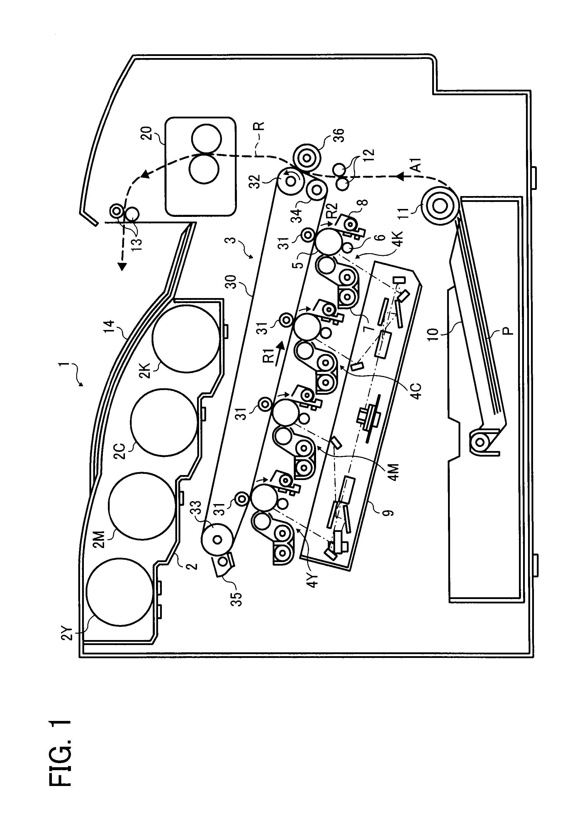
[0039]Referring now to the drawings, wherein like reference numerals designate identical or corresponding parts throughout the several views, in particular to FIG. 1, an image forming apparatus 1 according to an exemplary embodiment of the present invention is explained.

[0040]FIG. 1 is a schematic vertical sectional view of the image forming apparatus 1. The image forming apparatus 1 may be a copier, a facsimile machine, a printer, a multifunction peripheral or a multifunction printer (MFP) having at least one of copying, printing, scanning, facsimile, and plotter functions, or the like. Accord...


PUM


Abstract

A fixing device includes a fixing rotator rotatable in a predetermined direction of rotation and a nip formation assembly contacting an inner circumferential surface of the fixing rotator. An opposed rotator presses against the nip formation assembly via the fixing rotator to form a fixing nip between the fixing rotator and the opposed rotator, through which a recording medium is conveyed. A support, disposed opposite the inner circumferential surface of the fixing rotator, supports the nip formation assembly. A heater, disposed opposite the inner circumferential surface of the fixing rotator, heats the fixing rotator. A reflector, disposed opposite an outer circumferential surface of the fixing rotator, reflects heat radiated from the fixing rotator onto the fixing rotator. The reflector spans a circumferential span of the fixing rotator where the fixing rotator is spaced apart from the support with a decreased interval therebetween.

Description

CROSS-REFERENCE TO RELATED APPLICATIONS[0001]This patent application is based on and claims priority pursuant to 35 U.S.C. §119 to Japanese Patent Application Nos. 2013-103876, filed on May 16, 2013, and 2014-040326, filed on Mar. 3, 2014, in the Japanese Patent Office, the entire disclosure of each of which is hereby incorporated by reference herein.BACKGROUND[0002]1. Technical Field[0003]Exemplary aspects of the present invention relate to a fixing device and an image forming apparatus, and more particularly, to a fixing device for fixing an image on a recording medium and an image forming apparatus incorporating the fixing device.[0004]2. Description of the Background[0005]Related-art image forming apparatuses, such as copiers, facsimile machines, printers, or multifunction printers having two or more of copying, printing, scanning, facsimile, plotter, and other functions, typically form an image on a recording medium according to image data. Thus, for example, a charger uniforml...

Claims


Application Information

Patent Timeline
IPC IPC(8): G03G15/20
CPCG03G15/2053G03G2215/2035
Inventor YOSHIKAWA, MASAAKISEKI, TAKAYUKIARAI, YUJIYOSHINAGA, HIROSHIMIMBU, RYUUICHISESHITA, TAKUYATAMAKI, SHUNTAROYAMAMOTO, TAKESHIIMADA, TAKAHIROGOTOH, HAJIMESAITO, KAZUYAIKEBUCHI, YUTAKASHIMOKAWA, TOSHIHIKOYUASA, SHUUTAROHYAMAJI, KENSUKESUZUKI, AKIRA
Owner RICOH KK
Why Eureka
Try Eureka