
Pattern and surgery support set, apparatus, method and program

a technology of support set and surgical template, applied in the field of pattern and surgery support set, apparatus, method and program, can solve the problems of difficulty in knowing the place at which the template of an organ or a transparent film should be arranged, and the technique disclosed in patent document 3 does not satisfy a need, so as to achieve the effect of easy arrangement of the pattern

Active Publication Date: 2014-11-13
FUJIFILM CORP
View PDF7 Cites 12 Cited by
  • Summary
  • Abstract
  • Description
  • Claims
  • Application Information

AI Technical Summary

Benefits of technology

The present invention relates to a pattern for surgical support that includes an outer surface, an inner surface, and a guide wall for positioning an imaging probe. The pattern is designed to allow for easy placement on an organ and can help in identifying target portions of the organ for treatment. The guide wall connects the outer surface and inner surface of the pattern. The pattern can also be used with a reference image and can help in visual recognition of the tomographic image. Overall, the pattern provides improved accuracy and ease of placement for surgical procedures and supports operations with better precision.

Problems solved by technology

However, the techniques disclosed in Patent Documents 1, 2 and 4 have a problem that it is difficult to know a place at which a template of an organ or a transparent film should be arranged only based on external characteristics of the organ, for example, when the organ is a liver or the like.
Therefore, the technique disclosed in Patent Document 3 does not satisfy a need for arranging, at an appropriate position of the organ, a pattern indicating a treatment portion on a surface of the organ, which is set at a different position based on the position of the lesion and the purpose of treatment.

Method used


Image

  • Pattern and surgery support set, apparatus, method and program
  • Pattern and surgery support set, apparatus, method and program
  • Pattern and surgery support set, apparatus, method and program

Examples


Embodiment Construction

[0056]Hereinafter, a surgery support apparatus, a surgery support method, a surgery support program, a pattern and a surgery support set according to embodiments of the present invention will be described in detail with reference to drawings.

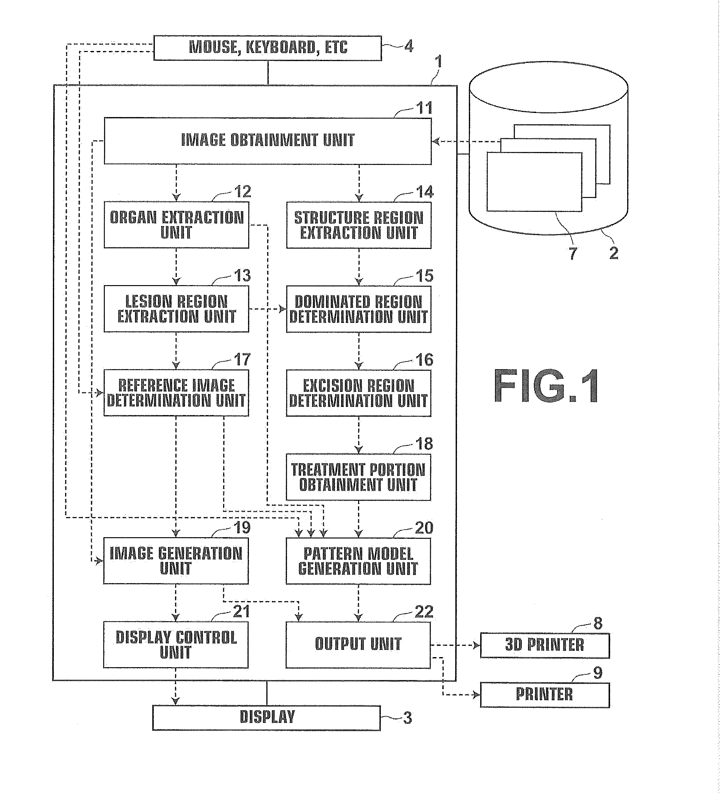
[0057]In each of the following embodiments, a surgery support apparatus 1 is a computer in which a surgery support program according to each of the embodiments has been installed. The computer may be a workstation or a personal computer directly operated by a doctor who performs diagnosis, or a server computer connected to them through a network. The surgery support program may be stored in a recording medium, such as a DVD and a CD-ROM, and distributed, and installed in a computer from the recording medium. Alternatively, the surgery support program may be stored in a storage apparatus of a server computer connected to a network or a network storage in a state of being accessible from the outside. Further, the surgery support program may be dow...


PUM


Abstract

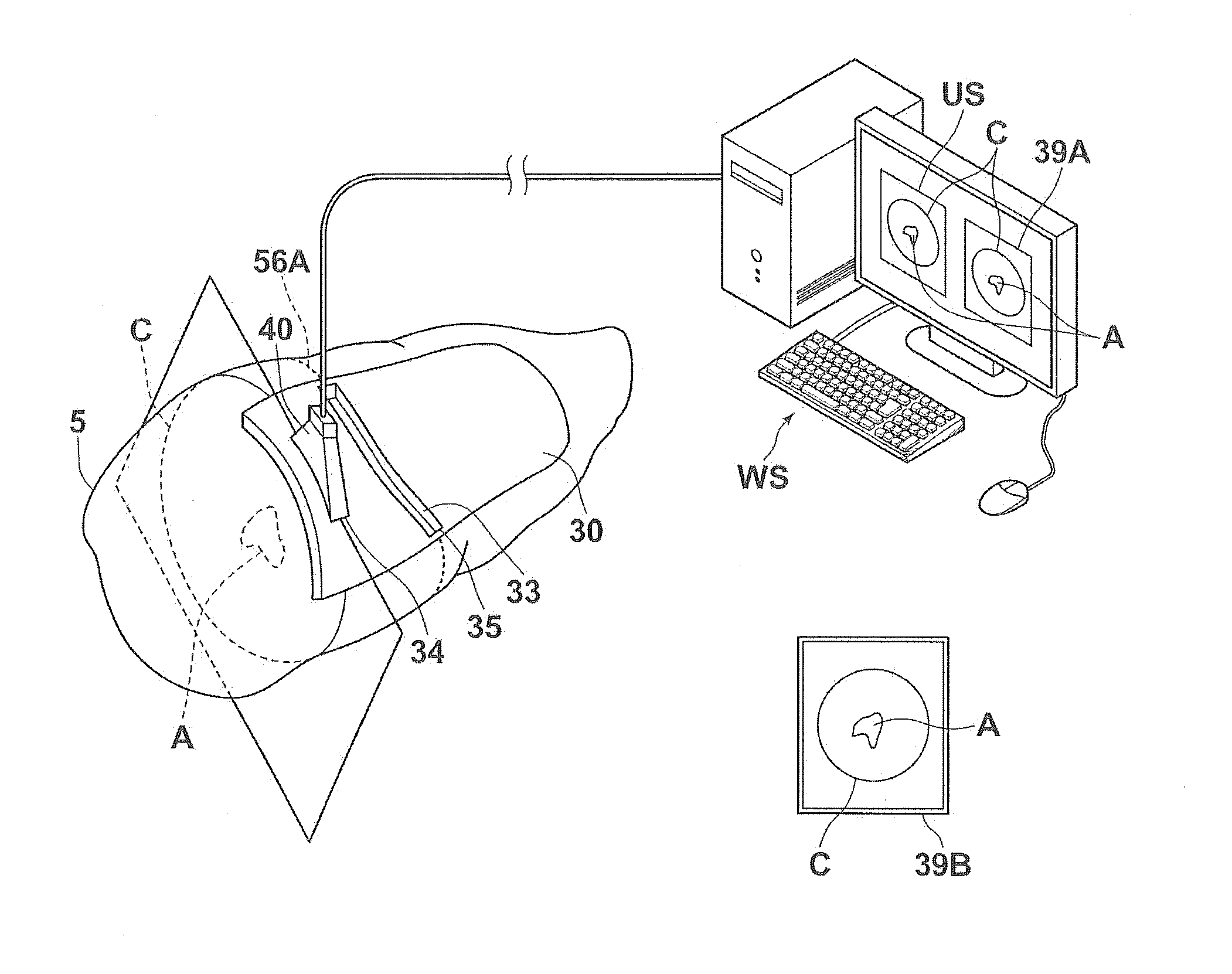
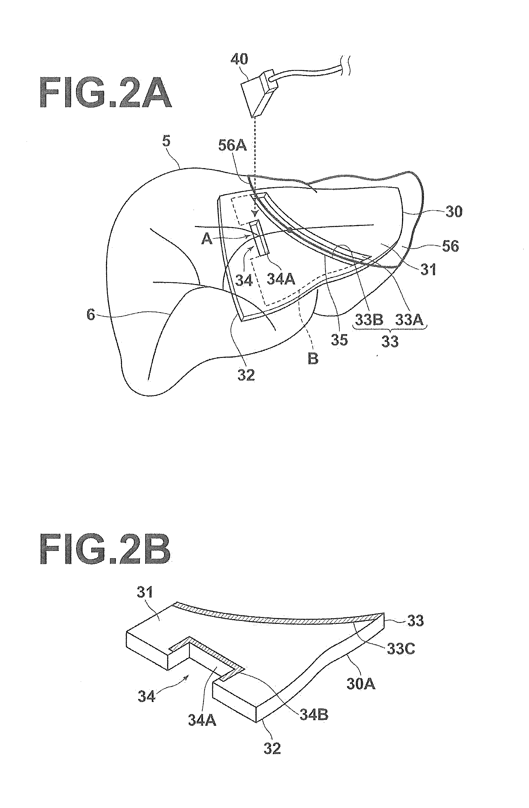
A three-dimensional image representing a patient's organ is obtained. The organ is extracted from the three-dimensional image. A treatment portion, at which desirable treatment for the organ is performed, on a surface of the organ is obtained. A pattern model including an outer surface, an inner surface having a surface form along an organ's outer surface of the organ, a guide wall connecting, along the treatment portion, the outer surface and the inner surface, and a positioning portion is generated. The positioning portion positions a predetermined imaging probe in such a manner that a tomographic image of a cross section of the organ including a target portion of the organ is imageable when the guide wall is arranged along the treatment portion on the organ.

Description

BACKGROUND OF THE INVENTION[0001]1. Field of the Invention[0002]The present invention relates to a pattern for supporting surgery by guiding a treatment position at which treatment is performed on an organ in surgery of the organ, and to a surgery support set, and to a surgery support apparatus, method and program.[0003]2. Description of the Related Art[0004]When surgery, such as excision of a part of a patient's organ, is performed, doctors determine an excision portion of the organ so as to include a lesion by checking the form of the organ and the position of the lesion in diagnosis using images before the surgery. Further, the doctors need to appropriately recognize, based on the determined excision portion, a treatment portion on a surface of the organ at which treatment, such as excision, should be performed, and to perform treatment, such as excision at the treatment portion.[0005]Japanese Unexamined Patent Publication No. 2011-172977 (Patent Document 1) and PCT Japanese Publ...

Claims


Application Information

Patent Timeline
IPC IPC(8): A61B19/00G06T17/00
CPCA61B19/50G06T17/00A61B2019/504A61B34/10A61B2034/104A61B2034/105A61B2034/108A61B2090/378A61B2090/3908A61B2090/3937
Inventor MIYAMOTO, MASAKI
Owner FUJIFILM CORP
Learn More