
Electrical harness connector

a technology of electrical harness and connector, which is applied in the direction of insulated conductors, cables, conductors, etc., can solve the problems of not even being able to remove the required part of a conventional harness, the connection may be relatively small and/or lightweight, and the amount of conventional harness is bulky, etc., to achieve the effect of reducing (or substantially eliminating) the amount, reducing vibration, and prolonging the life of the electrical ra

Active Publication Date: 2014-11-06
ROLLS ROYCE PLC
View PDF8 Cites 10 Cited by
  • Summary
  • Abstract
  • Description
  • Claims
  • Application Information

AI Technical Summary

Benefits of technology

The patent text describes the need for a way to connect electrical cables to each other in a way that is strong and reliable, especially in safety-critical applications like gas turbine engines. This is important because the environment in which these engines operate can be very harsh, with high temperatures and vibration.

Problems solved by technology

This makes the conventional harness bulky, heavy and difficult to manipulate.
This may be particularly important for gas turbine engine applications, which may be safety-critical and subject to a harsh environment, such as high levels of temperature and vibration.
Such a connection may be relatively small and / or lightweight, for example because it may only be necessary to provide enough insulating material as required to seal the connection formation.
For example, some maintenance procedures may only require access to a certain portion of the gas turbine engine that only requires a part of the harness to be removed.
It may be difficult and / or time consuming, or not even possible, to only remove the required part of a conventional harness from a gas turbine engine.
However, it may be relatively straightforward to only remove the relevant electrical raft, for example by simply disconnecting it from the engine and any other electrical rafts / components to which it is connected.
Such a rigid composite material may be particularly stiff and / or lightweight.
The environment of a gas turbine engine during operation may be particularly severe, with, for example, high levels of vibration and / or differential expansion between components as the temperature changes through operation and as the components move relative to each other.

Method used


Image

  • Electrical harness connector
  • Electrical harness connector
  • Electrical harness connector

Examples


Embodiment Construction

[0087]FIG. 8 shows schematically a portion of an electrical harness 200 formed from a flexible printed circuit 201 which provides a plurality of conductive tracks 203, optionally in multiple layers. The portion ends at a terminating region 205. In the example of FIG. 8, the terminating region is substantially planar and disc shaped. The conductive tracks fan out in the terminating region 205 of FIG. 8 and join to respective receiving holes 207 which penetrate through the terminating region perpendicularly to the plane of the region. The holes are internally plated with an electrically conductive layer 221.

[0088]FIG. 9 shows schematically a transverse longitudinal cross-sectional view through an assembly of two electrical harnesses 200 that are electrically connected together. The assembly comprises a connection formation 250, at which the two electrical harnesses 200 of the type shown in FIG. 8 are electrically connected together via their terminating regions 205.

[0089]The connectio...


PUM

PropertyMeasurementUnit
Flexibilityaaaaaaaaaa
Moldableaaaaaaaaaa
Electrical conductoraaaaaaaaaa

Abstract

An electrical connection between two electrical harnesses is provided. The electrical harnesses include flexible printed circuits with embedded conductive tracks, each of which terminates in a receiving hole in a respective terminating region The terminating regions are connected together using conductive pins. The connection formation is then encapsulated by an encapsulating body formed of an insulating. The encapsulating body seals and protects the electrical connection, which is thus reliable and robust.

Description

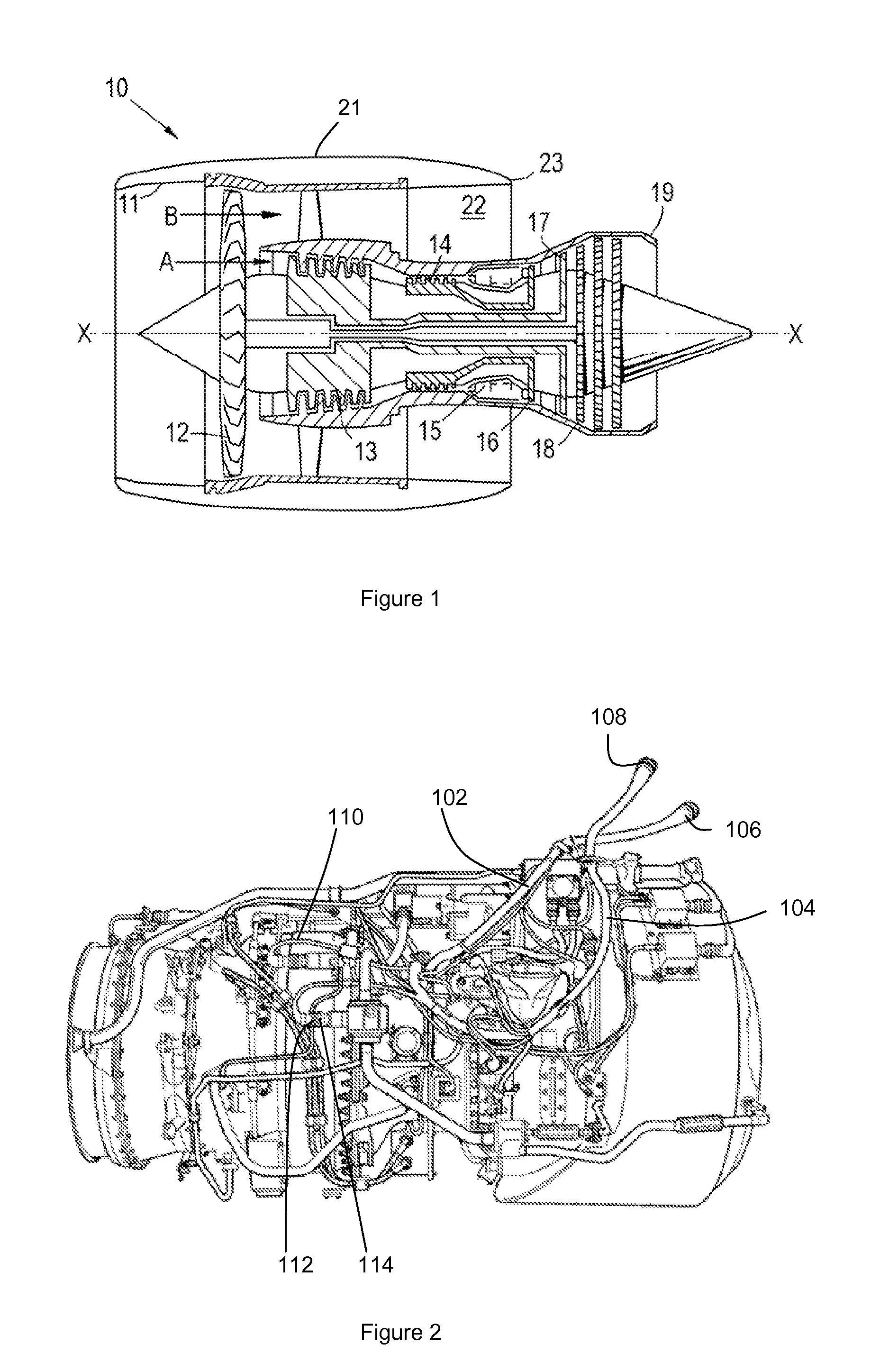
CROSS-REFERENCE TO RELATED APPLICATIONS[0001]This application is based upon and claims the benefit of priority from British Patent Application Number 1308028.8 filed 3 May 2013, the entire contents of which is incorporated by reference.BACKGROUND OF THE INVENTION[0002]1. Field of the Disclosure[0003]The present invention relates to connecting two electrical harnesses together, each harness being formed from a flexible printed circuit which provides a plurality of conductive tracks.[0004]2. Description of the Related Art[0005]With reference to FIG. 1, a ducted fan gas turbine engine generally indicated at 10 has a principal and rotational axis X-X. The engine comprises, in axial flow series, an air intake 11, a propulsive fan 12, an intermediate pressure compressor 13, a high-pressure compressor 14, combustion equipment 15, a high-pressure turbine 16, and intermediate pressure turbine 17, a low-pressure turbine 18 and a core engine exhaust nozzle 19. A nacelle 21 generally surrounds ...

Claims


Application Information

Patent Timeline
IPC IPC(8): H01B7/00H05K3/36
CPCH05K3/361H01B7/0045H01R12/52H01R12/613F02C7/32F05D2220/76F05D2260/30H05K1/144H05K1/147H05K3/363H05K2201/058Y10T29/49126Y02T50/60
Inventor BROUGHTON, PAUL
Owner ROLLS ROYCE PLC
Learn More