
Rectified Stereoscopic 3D Panoramic Picture

a stereoscopic and panoramic picture technology, applied in the field of digital frame processing, can solve problems such as eye fatigue for viewers and problematic different perspectives, and achieve the effect of easy computation of global transformation

Active Publication Date: 2014-11-06
TELEFON AB LM ERICSSON (PUBL)
View PDF9 Cites 4 Cited by
  • Summary
  • Abstract
  • Description
  • Claims
  • Application Information

AI Technical Summary

Benefits of technology

The present invention is a method for compensating for differences in perspective between different panoramic pictures. It determines a frame among already acquired frames that has a common area with the current frame. The difference of perspective is then evaluated to compensate it by applying a global transform. This results in an improved final stereoscopic image that is non-distorted, natural, and does not cause eye fatigue. The method is efficient and not time-consuming or resource-consuming.

Problems solved by technology

However, the different perspectives are problematic when several panoramic pictures are created, for stereoscopic panoramic pictures for example.
The result of perspective differences is that a final stereoscopic image, obtained based on the two panoramic pictures, will look distorted, unnatural, and the depth effect may be difficult to perceive, thus creating eye fatigue for a viewer.

Method used


Image

  • Rectified Stereoscopic 3D Panoramic Picture
  • Rectified Stereoscopic 3D Panoramic Picture
  • Rectified Stereoscopic 3D Panoramic Picture

Examples


Embodiment Construction

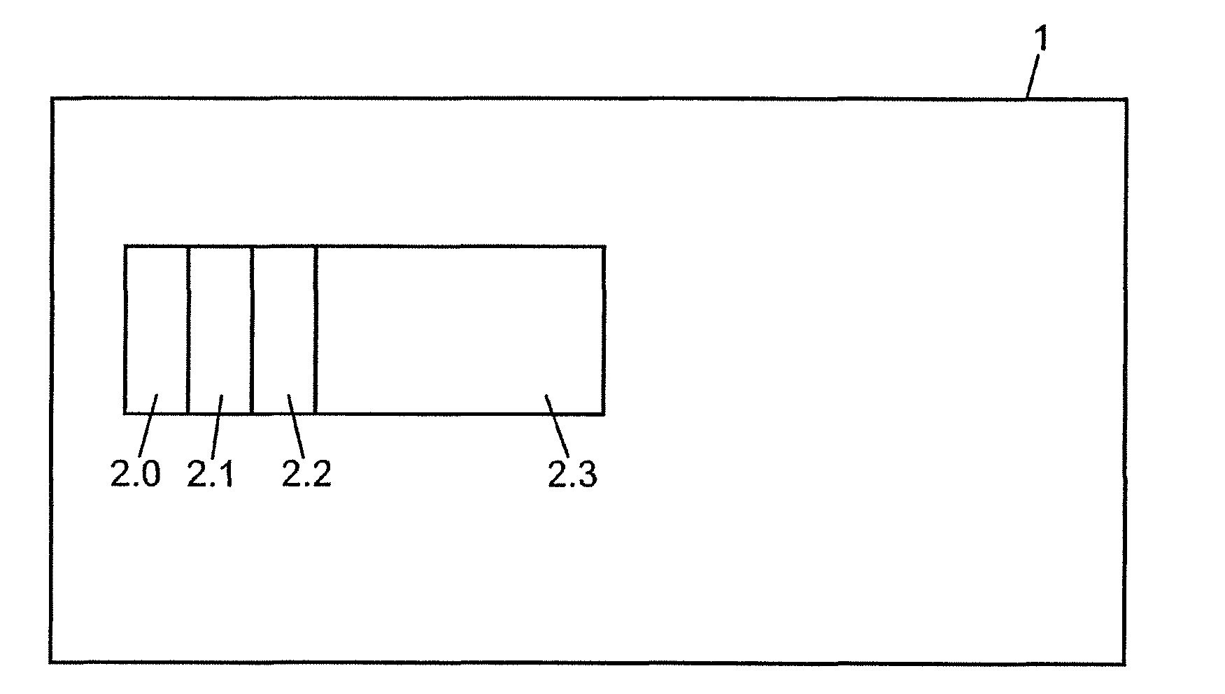
[0062]Referring to FIG. 1, there is shown a panoramic picture 1 comprising a series of frames that have been captured by a single camera. The frames may be still images that have been successively captured or frames that originate from a video sequence. In the present example, the panoramic picture 1 has a rectangular shape. However, no restriction is attached to the shape of the panoramic picture, which depends on what a user of the camera wants to create.

[0063]The series of frames comprises frames 2.0, 2.1, 2.2 and 2.3. In the example represented on FIG. 1, the frames have been recorded while the camera is panned from the left to the right. No restriction is attached to the direction and the sense in which the camera is panned (from the right to the left, from top to down, bottom-up, passing several times on the same view, coming back to a same view etc).

[0064]The frames 2.0-2.3 have been successively included into the panoramic picture 1 and superimposed in positions that depend ...


PUM


Abstract

The invention concerns a method of generating at least a first panoramic picture and a second panoramic picture based on a series of frames acquired by one frame acquisition device while said device is panned in a main direction, a global motion value and a perspective transform being computed for each pair of consecutive frames of the series, the global motion value reflecting a displacement in the main direction between the frames of a pair of frames and the perspective transform reflecting a perspective change between the frames of a pair of frames. For each frame of the series, a first area of the frame is determined for the first panoramic picture and a second area of the frame, distinct from the first area, is determined for the second panoramic picture. The method comprises, upon acquisition of a current frame of the series of frames, determining a first frame among the already acquired frames of the series of frames, which has second area that shares at least a common area with the first area of the current frame, calculating a global transform based on the perspective transforms of the pairs of consecutive frames that have been acquired between the first frame and the current frame and determining an adapted first area by applying an inverse of the global transform to the first area of the current frame, the adapted first area being included into the first panoramic picture and the second area of the current frame being included into the second panoramic picture.

Description

BACKGROUND[0001]1. Technical Field[0002]The present invention generally relates to digital frame processing and in particular to panoramic frame processing.[0003]It finds application in particular, while not exclusively, in picture acquisition devices and in particular, while not exclusively, in single lens devices.[0004]2. Related Art[0005]The approaches described in this section could be pursued, but are not necessarily approaches that have been previously conceived or pursued. Therefore, unless otherwise indicated herein, the approaches described in this section are not prior art to the claims in this application and are not admitted to be prior art by inclusion in this section.[0006]Panoramic pictures or mosaics are larger images formed by assembling smaller still or video frames according to a single given direction (e.g. left to right) imposed by the movement of the camera that captured the sequence of frames. The sequence of frames can be acquired by a camera that is rotated ...

Claims


Application Information

Patent Timeline
Patent Type & Authority Applications(United States)
IPC IPC(8): H04N5/225H04N13/02H04N13/221
CPCH04N5/2259H04N13/0203G06T3/4038H04N9/76H04N13/221H04N13/204H04N23/58
Inventor DROUOT, ANTOINE
Owner TELEFON AB LM ERICSSON (PUBL)
Learn More