Base, full-line printhead, and printing apparatus

Active Publication Date: 2014-11-06
CANON KK
View PDF2 Cites 0 Cited by
  • Summary
  • Abstract
  • Description
  • Claims
  • Application Information

AI Technical Summary

Benefits of technology

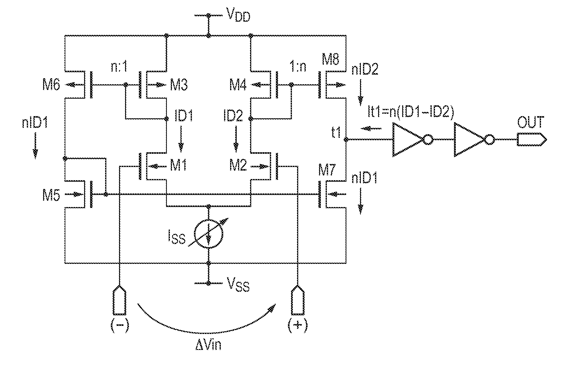
The invention is about a printing apparatus that can make the waveform quality of signals connected in a one-to-one or one-to-many connection match each other, and ensure a sufficient margin of "setup / hold time." This allows for accurate data reception and ensures optimal operation for each element substrate. The printing width is achieved by using a base and a full-line printhead, which has a plurality of driving elements that act as print elements. The invention advantageously allows for coincidence of waveform quality between signals connected in a one-to-one or one-to-many connection by changing the amplifier gain.

Problems solved by technology

Hence, when an amplitude difference between the image data signal and the clock signal occurs, it results in a difference between the rise and fall of the single-ended signal after amplification by the reception circuit.
For this reason, it results in a difference between the rise and fall of the single-ended waveform after amplification by the reception circuit.
As a consequence, the margin of Setup / Hold time of the image data signal and the clock signal becomes small, and the element substrate might be no longer able to receive a correct data signal.

Method used


Image

  • Base, full-line printhead, and printing apparatus
  • Base, full-line printhead, and printing apparatus
  • Base, full-line printhead, and printing apparatus

Examples


first embodiment

[0058]FIG. 7 is a circuit diagram showing the circuit layout and wiring of four element substrates integrated on a printed board 110.

[0059]As shown in FIG. 7, four element substrates 101 are arranged on the printed board 110. A first pair of signal lines 106 configured to supply a clock signal (CLK) and four second pairs of signal lines 107 configured to supply image data signals (DATA) are formed on the printed board 110. Note that the printed board 110 is also called a base because a plurality of element substrates are arranged and integrated on it.

[0060]The first pair of signal lines 106 supply a common signal to the element substrates and therefore form one-to-many connection from the viewpoint of the wiring space of the printed board. On the other hand, the four second pairs of signal lines 107 form one-to-one connection because the element substrates use individual signals. The first pair of signal lines 106 are terminated by a terminating resistor 108-1. The second pairs of s...

second embodiment

[0082]FIG. 12 is a circuit diagram showing the circuit layout and wiring of four element substrates integrated on a printed board 110 according to the second embodiment. In this embodiment as well, four element substrates 101 having the same circuit arrangement are arranged on the printed board 110, as in the first embodiment. The same reference numerals and symbols as in the first embodiment denote the same constituent elements and signals in FIG. 12, and a detailed description thereof will be omitted.

[0083]The element substrate is different from that of the first embodiment shown in FIG. 7 in that two control circuits 105-1 and 105-2 and control terminals 109-1 and 109-2 corresponding to them are provided in each element substrate.

[0084]The wiring of the printed board 110 is different from that of the first embodiment in that two second pairs of signal lines 107 are provided, and image data signals (DATA) are also supplied by the two second pairs of signal lines 107 of one-to-many...


PUM


Abstract

A full-line printhead includes a base in which a plurality of substrates each including arrayed print elements are arranged in the arrayed direction has the following arrangement. The base includes a terminal for inputting a first differential signal, a first pair of lines for transferring the first differential signal from the terminal to the substrates, a terminal for inputting a second differential signal, and a second pair of lines for transferring the second differential signal from the terminal to the substrates. Each substrate includes a first amplifier for amplifying the first differential signal transferred via the first pair of lines, and a second amplifier for amplifying the second differential signal transferred via the second pair of lines. Control is performed to change the gain of the first amplifier based on a control signal from outside.

Description

BACKGROUND OF THE INVENTION[0001]1. Field of the Invention[0002]The present invention relates to a base, a full-line printhead, and a printing apparatus and, more particularly, to a full-line printhead that performs printing in accordance with, for example, an inkjet method and a printing apparatus that performs printing using the same.[0003]2. Description of the Related Art[0004]The element substrate of a printhead included in an inkjet printing apparatus (to be referred to as a printing apparatus hereinafter) is formed from a semiconductor integrated circuit. To implement printing at a higher speed, there has been proposed a full-line printhead in which a plurality of element substrates are arranged to obtain a print width equal to or more than the width of a print medium in advance. For example, Japanese Patent Laid-Open No. 2011-046160 discloses such a full-line printhead.[0005]As a clock signal (CLK) used to supply an image data signal (DATA) or a latch signal (LT) to the eleme...

Claims


Application Information

Patent Timeline
IPC IPC(8): B41J2/115
CPCB41J2/115B41J2/04541B41J2/0458B41J2202/20B41J2202/21
Inventor UMEDA, KENGO
Owner CANON KK
Why Eureka
Try Eureka