
Apparatus and method for wireless charging

a wireless charging and apparatus technology, applied in the direction of battery overcharge protection, safety/protection circuit, transportation and packaging, etc., can solve the problems of deteriorating wireless charging efficiency, power transfer efficiency decline, and lower convenience of induction methods compared with wire charging methods

Inactive Publication Date: 2014-11-06
ELECTRONICS & TELECOMM RES INST
View PDF3 Cites 270 Cited by
  • Summary
  • Abstract
  • Description
  • Claims
  • Application Information

AI Technical Summary

Benefits of technology

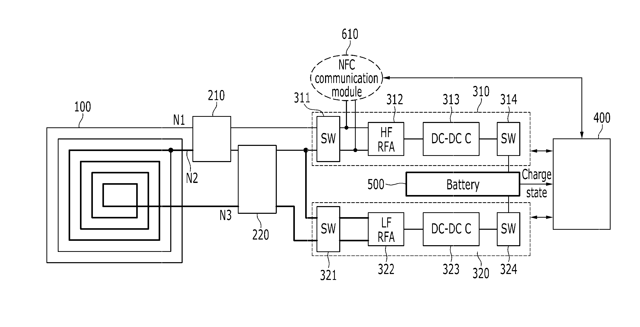
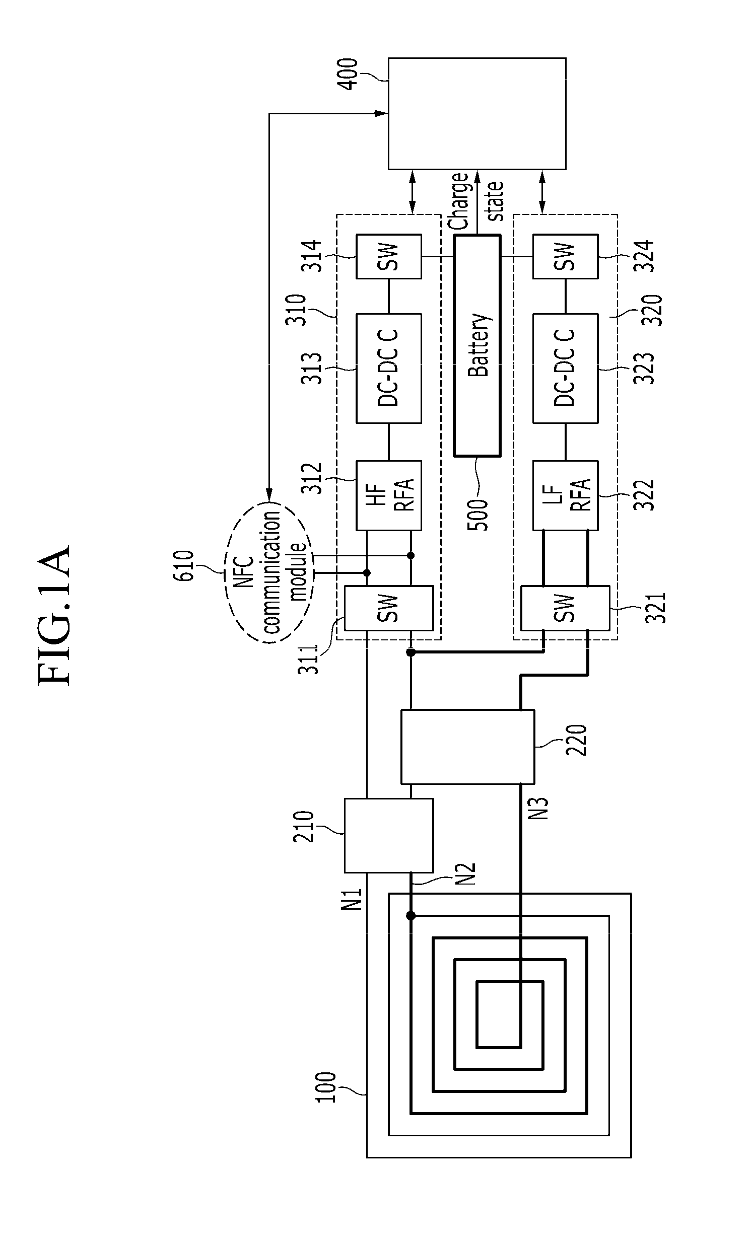
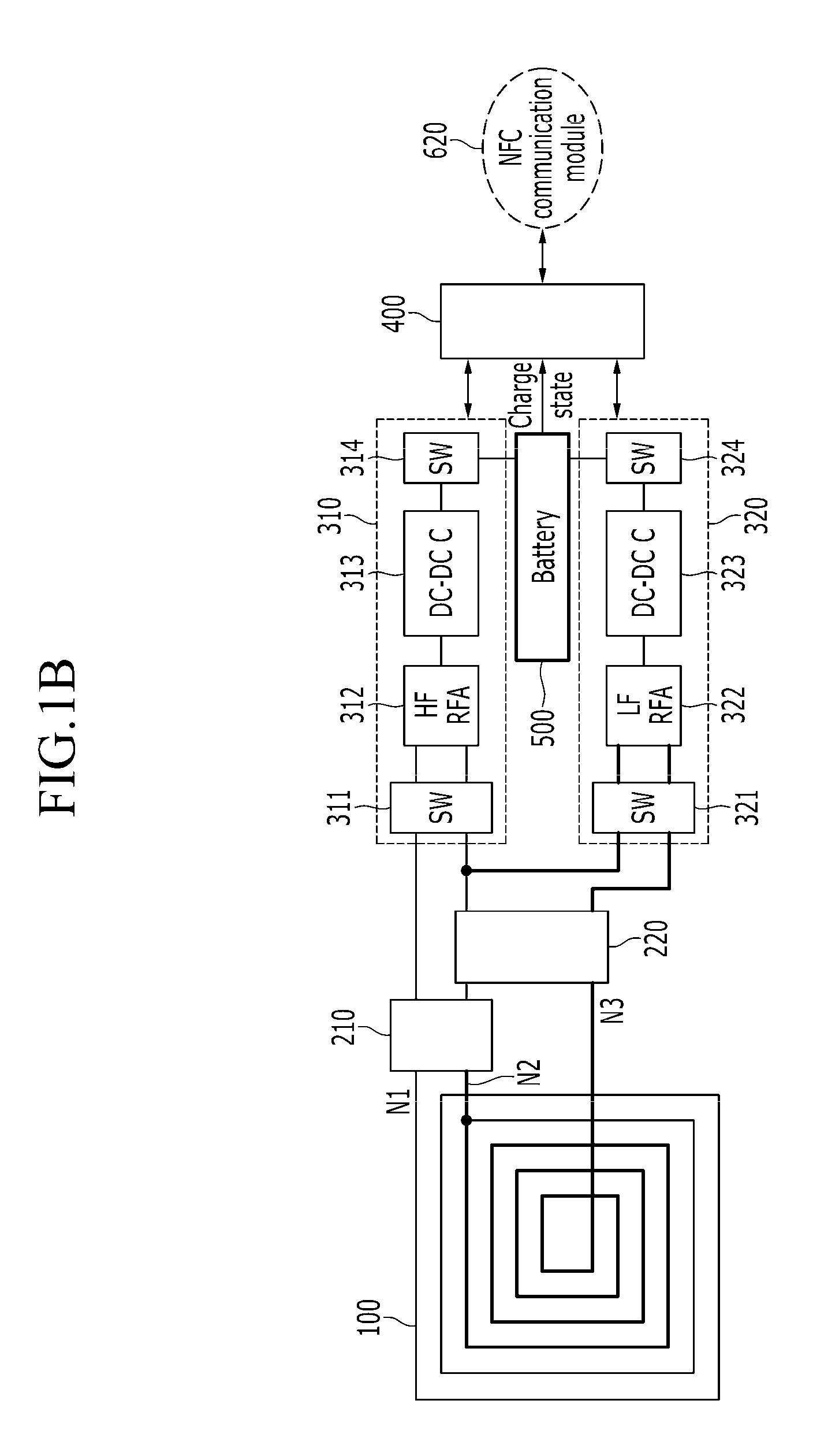
The present invention provides a wireless charging method and apparatus that can use multiple frequencies for wireless charging. The wireless charging apparatus includes an antenna, two charging power generators, and a controller that senses the frequency of the electrical waves received through the antenna and activates the appropriate charging power generator based on the sensed result. The wireless charging method involves receiving electrical waves, determining the frequency band, and activating the appropriate charging power generator. The technical effects of the invention include improved wireless charging efficiency and flexibility.

Problems solved by technology

The resonance method is advantageous in view of charging distance, but has difficulty in realizing a high Q value and thus has a drawback that power transfer efficiency decreases.
That is, because the induction method has a much shorter charging distance than that of the resonance method, the induction method has lower convenience, compared with a wire charging method.
In a terminal (e.g., a smart phone) in which a near field communication (NFC) communication chip using a frequency band of 13.56 MHz is separately mounted, a 125 KHz antenna for wireless charging and a 13.56 MHz antenna for NFC communication should separately exist, but because of complexity and interference due to two antennas, efficiency of wireless charging may be deteriorated.
Further, there is a drawback that conventional wireless charging technology performs wireless charging using only one frequency.

Method used


Image

  • Apparatus and method for wireless charging
  • Apparatus and method for wireless charging
  • Apparatus and method for wireless charging

Examples


Embodiment Construction

[0030]In the following detailed description, only certain exemplary embodiments of the present invention have been shown and described, simply by way of illustration. As those skilled in the art would realize, the described embodiments may be modified in various different ways, all without departing from the spirit or scope of the present invention. Accordingly, the drawings and description are to be regarded as illustrative in nature and not restrictive. Like reference numerals designate like elements throughout the specification.

[0031]A receiving wireless charging apparatus according to an exemplary embodiment of the present invention performs wireless charging using two or more frequency bands. Hereinafter, for convenience of description, a case in which a receiving wireless charging apparatus according to an exemplary embodiment of the present invention uses two frequency bands, i.e., a frequency for NFC communication (hereinafter, an “NFC frequency”) of a 13.56 MHz band, which ...


PUM


Abstract

A wireless charging apparatus is provided. The wireless charging apparatus includes: an antenna that receives electrical waves; at least two charging power generators that generate charging power for charging a battery using the electrical waves received through the antenna; and a controller that senses a frequency of the electrical waves received through the antenna and that activates one of the at least two charging power generators according to a sensed result.

Description

CROSS-REFERENCE TO RELATED APPLICATION[0001]This application claims priority to and the benefit of Korean Patent Application No. 10-2013-0049595 filed in the Korean Intellectual Property Office on May 2, 2013, the entire contents of which are incorporated herein by reference.BACKGROUND OF THE INVENTION[0002](a) Field of the Invention[0003]The present invention relates to a wireless charging method and an apparatus for charging a battery by wireless.[0004](b) Description of the Related Art[0005]Wireless charging technology in which a user can conveniently charge many electric apparatuses such as various mobile terminals, small household goods, and toys by wireless is requested. Wireless charging technology is technology in which a radio frequency is received and in which a DC voltage that can be used in a system or a device power supply apparatus is generated. In general, a wireless charging method is classified into an induction method and a resonance method. Conventional wireless c...

Claims


Application Information

Patent Timeline
Patent Type & Authority Applications(United States)
IPC IPC(8): H02J7/02
CPCH02J7/025H02J50/12H02J7/00302H02J7/00308H02J50/80H02J50/90H04B5/79H02J50/10
Inventor PARK, JI MANLEE, KANG BOKBAEK, KYU-HA
Owner ELECTRONICS & TELECOMM RES INST
Learn More