LED drive device, and lighting system incorporating the same

a technology of led drive and drive device, which is applied in the direction of electroluminescent light source, electric lighting source, and use of semiconductors. it can solve the problems of not meeting specific safety standards, different forward bias voltages may not be suitable for direct use in display devices or illumination devices without operating power control, etc., and achieve stable operating power

Inactive Publication Date: 2014-11-06
ILI TECHNOLOGY CORPORATION
View PDF2 Cites 3 Cited by
  • Summary
  • Abstract
  • Description
  • Claims
  • Application Information

AI Technical Summary

Benefits of technology

[0007]Therefore, an object of the present invention is to provide an LED drive device, and a lighting system incorporating the same that can ensure an LED-based load to have a relatively stable operating power.

Problems solved by technology

Thus, if a constant current flows through each of such LEDs, operating powers generated by such LEDs may not be within a desired power range.
As a result, electronic products employing such LEDs may not comply with specific safety standards due to variations in the operating powers of such LEDs as induced by variations in the forward bias voltages of such LEDs.
Therefore, LEDs having different forward bias voltages may be unsuitable to be directly employed in a display device or an illumination device without operating power control.

Method used


Image

  • LED drive device, and lighting system incorporating the same
  • LED drive device, and lighting system incorporating the same
  • LED drive device, and lighting system incorporating the same

Examples


Embodiment Construction

[0024]Before describing this invention in detail, it should be noted herein that throughout this disclosure, when two elements are described as being “coupled in series,”“connected in series” or the like, it is merely intended to portray a serial connection between the two elements without necessarily implying that the currents flowing through the two elements are identical to each other and without limiting whether or not an additional element is coupled to a common node between the two elements. Essentially, “a series connection of elements,”“a series coupling of elements” or the like as used throughout this disclosure should be interpreted as being such when looking at those elements alone.

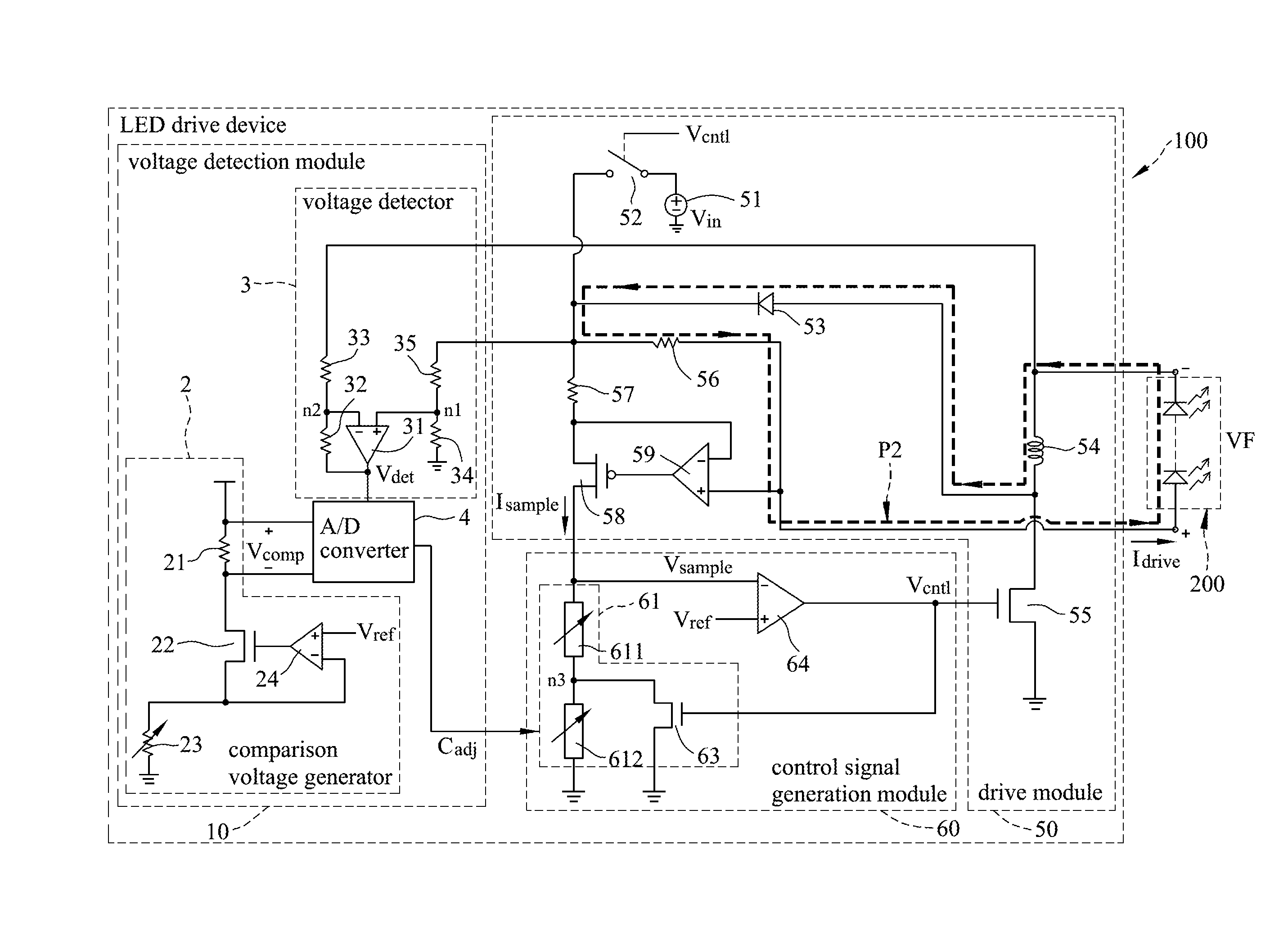
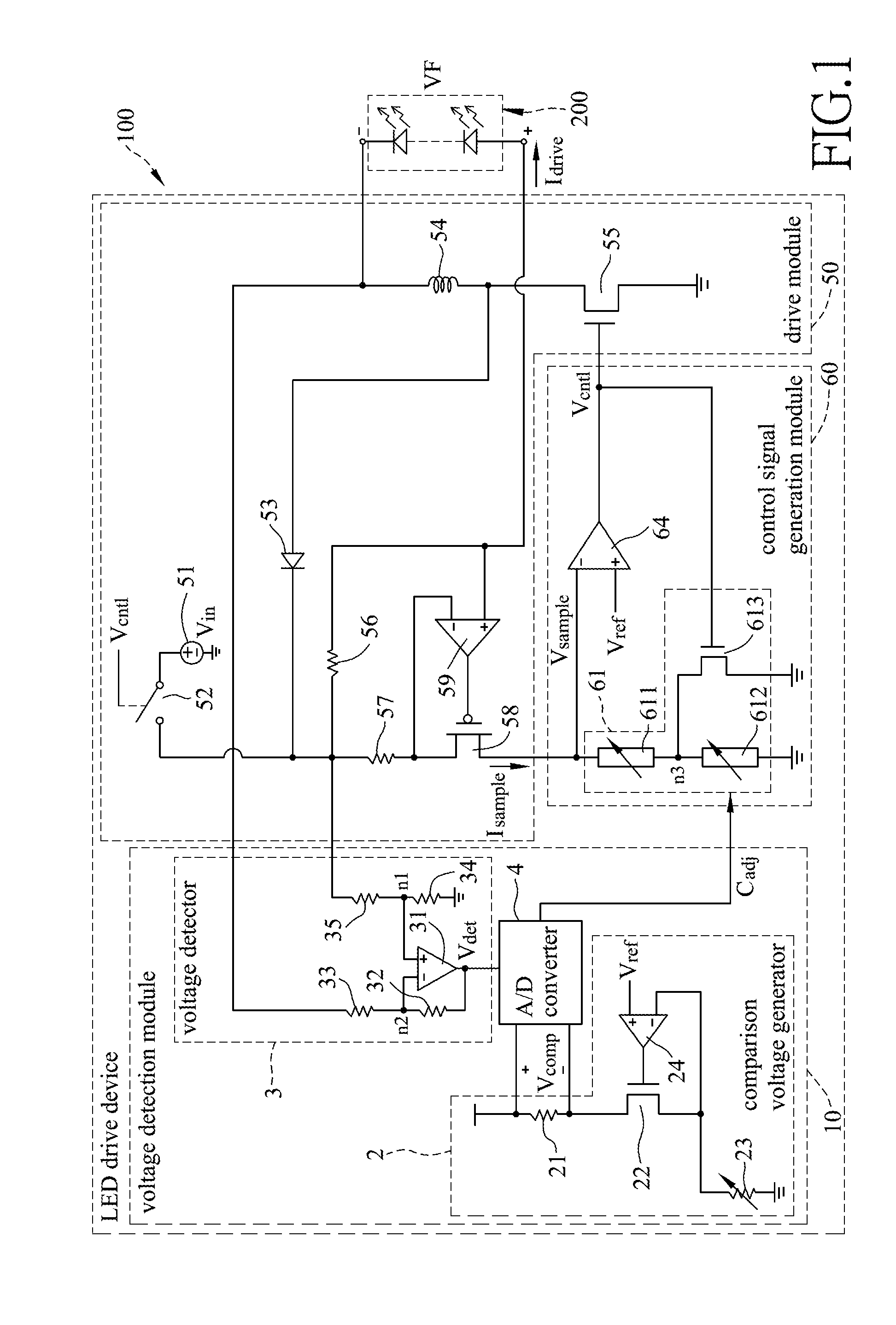
[0025]Referring to FIG. 1, the preferred embodiment of a lighting system according to the present invention is shown to include an LED-based load 200 and an LED drive module 100.

[0026]The LED-based load 200 has opposite positive and negative terminals. In this embodiment, the LED-based load 200...


PUM


Abstract

An LED drive device includes: a drive module generating, based on a control signal, a drive current that flows through an LED-based load, and generating, based on the drive current, a sampling current associated with the drive current; a voltage detection module detecting a voltage across the LED-based load, and generating an adjustment signal based on the detection result and on a predetermined reference voltage; and a control signal generation module generating the control signal based on the adjustment signal, the sampling current and the predetermined reference voltage.

Description

CROSS-REFERENCE TO RELATED APPLICATION[0001]This application claims priority to Taiwanese Application No. 102116055, filed on May 6, 2013, the contents of which are hereby incorporated by reference.BACKGROUND OF THE INVENTION[0002]1. Field of the Invention[0003]The invention relates to optical power control for a light emitting diode (LED), and more particularly to an LED drive device, and a lighting system incorporating the same.[0004]2. Description of the Related Art[0005]In recent years, LEDs have been widely applied to electronic devices, such as display devices and illumination devices, for energy-saving and environment protection purposes. LEDs employed in such electronic devices should have a stable operating power.[0006]However, LEDs may be fabricated to have respective forward bias voltages different from a predetermined target forward bias voltage due to process drift. Thus, if a constant current flows through each of such LEDs, operating powers generated by such LEDs may ...

Claims


Application Information

Patent Timeline
Patent Type & Authority Applications(United States)
IPC IPC(8): H05B33/08H05B44/00
CPCH05B33/0815H05B45/10Y02B20/30H05B45/3725H05B45/14
Inventor LIU, WEN-KUENYU, CHUN-CHIEH
Owner ILI TECHNOLOGY CORPORATION
Why Eureka
Try Eureka