Panel rack support and protective system for stacking

a technology of solar panel and support rod, which is applied in the direction of solar heat collector safety, pv power plants, lighting and heating equipment, etc., can solve the problems of increasing the cost of the overall solar panel system, affecting the maintenance of the panel spacing, and the chance of damage or degradation of the solar panel during transport and installation, etc., to achieve convenient installation and maintenance, easy addition to various parts of the solar panel array, and easy removal

Inactive Publication Date: 2014-10-30
NORTHERN STATES METALS
View PDF19 Cites 11 Cited by
  • Summary
  • Abstract
  • Description
  • Claims
  • Application Information

AI Technical Summary

Benefits of technology

[0019]It is again an additional object of the present invention to provide a solar panel protection system that facilitates maintenance of panel spacing at all times, including deployment of solar panel populated support rack sections at various angles.
[0020]It is yet another object of the present invention to provide a solar panel protection and alignment system that can be easily added to various

Problems solved by technology

However, there are prosaic factors dictated by the market conditions, rather than technology.
These include the expense and ease of installation, and the allocation of capital investment to installation contractors.
A major factor in this cost benefit analysis is the chance of destruction or degradation of the solar panels during transport and installation.
Currently, the solar panel market has evolved to the point that installation costs from a contracting installer constitutes a major capital expenditure that has substantially added to the cost of the overall solar panel system.
Installation costs from contractors typically constitute a fixed expenditure in the purchase of solar panel arrays.
Unfortunately, improvements in the base of installation of solar panel support structures do very little to change this apparent fixed cost.
This has always constituted a major difficulty since assembly of the solar panel array was often inaccurate, always very time-consuming, and occasionally constituted a hazard to both personnel and the delicate solar panels themselves.
While this arrangement saved a great deal of time and installation expense, it made little impact in the market where installation costs were always fixed regardless of the type of support sy

Method used


Image

  • Panel rack support and protective system for stacking
  • Panel rack support and protective system for stacking
  • Panel rack support and protective system for stacking

Examples


Embodiment Construction

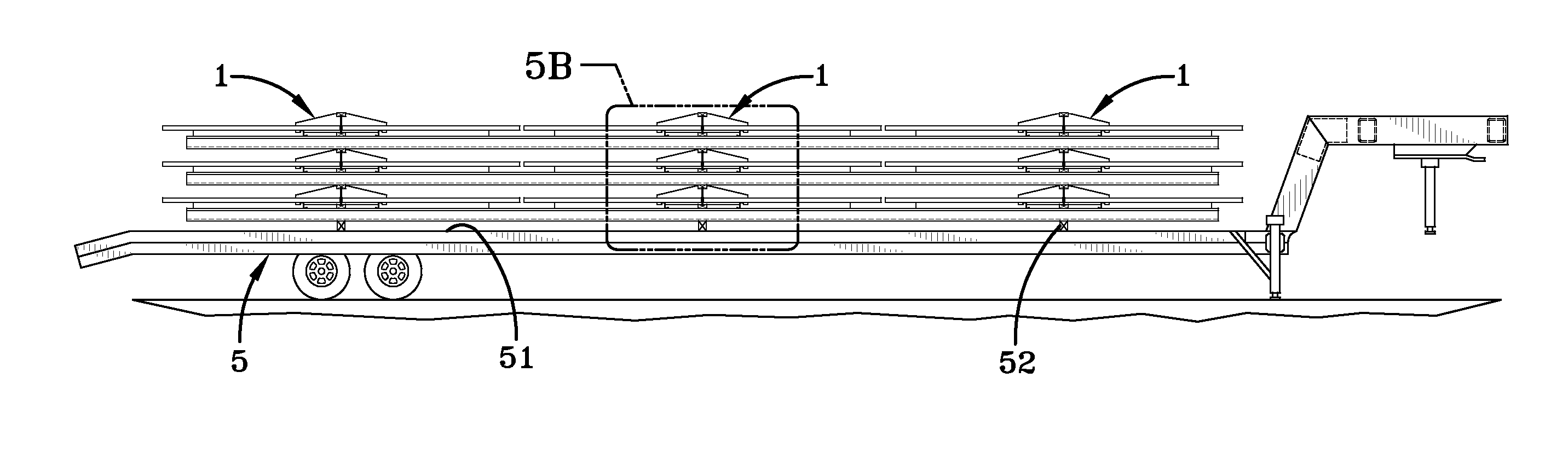
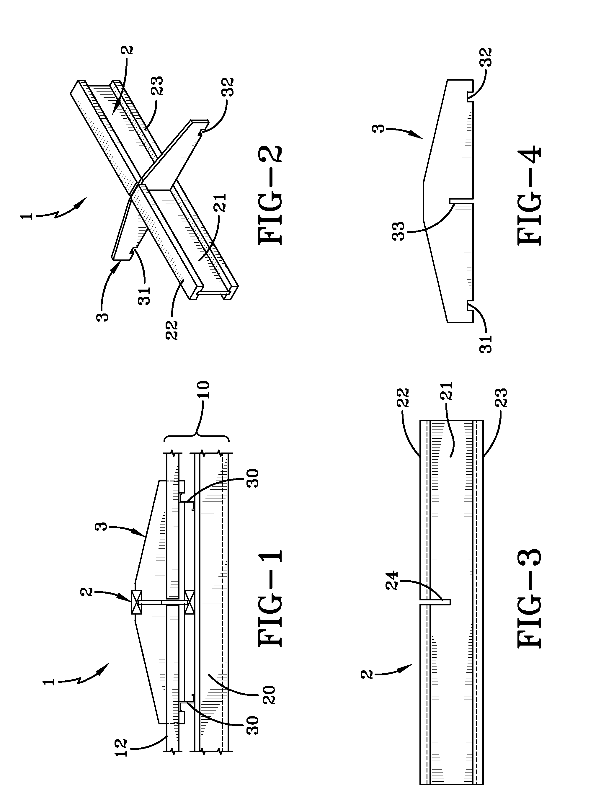
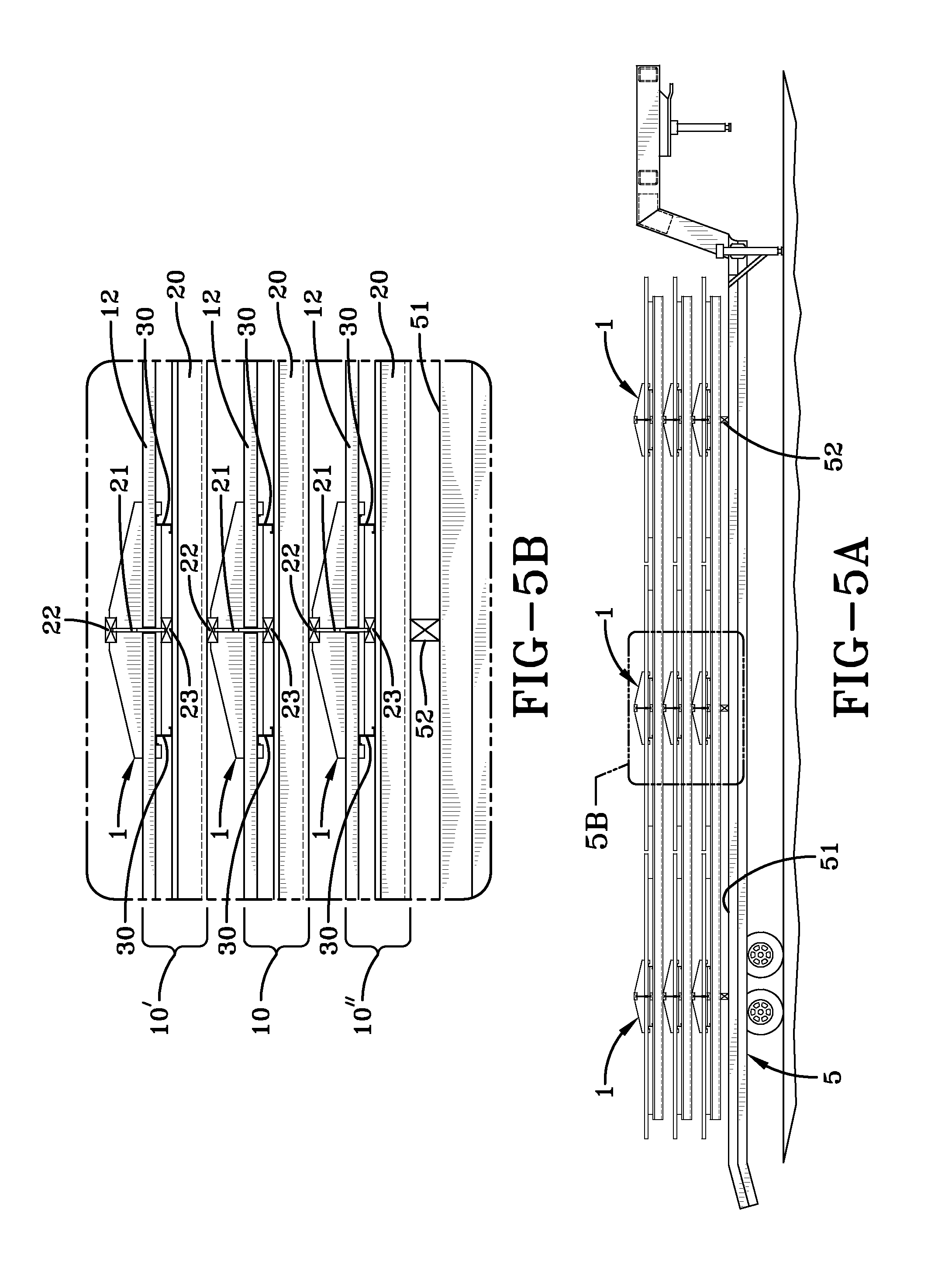
[0043]The solar panel protection and alignment system of the present invention relies upon selective deployment of crib structures 1 on a solar panel-populated section of a panel support array. Generally, a solar panel support array is constituted by an upper panel rail 30 (vertical Z-rail) and an underlying lower support joist 20 (horizontal Z-purlin). The upper panel rail 30 directly supports solar panel modules 12. These modules can be framed or unframed, and can be attached to the panel rail 30 using a wide variety of techniques. These include panel clips, screws through the frame (not shown) of solar panel module 12, and adhesive holding the active portion of the solar panel directly to panel rail 30.

[0044]It should be understood that the upper panel rail 30, while depicted as a Z-purlin, can be virtually any structure that will be appropriate to support a solar panel module 12. Likewise, the lower support joist 20 can be a Z-purlin, or can be constituted by any appropriate str...


PUM


Abstract

A solar panel protection and alignment system is constituted by the deployment of at least one crib structure between four adjacent solar panels. The crib structure includes two interlocking perpendicular pieces providing support and panel alignment.

Description

PRIORITY INFORMATION[0001]The present application claims priority to U.S. Provisional Patent Application No. 61 / 817,412 filed Apr. 30, 2013, incorporated herein in its entirety.FIELD OF INVENTION[0002]The present invention relates generally to the field of panel support and protection. In particular, the present invention is directed to a system for aligning and protecting solar panels during transit from a first location for subsequent assembly and / or installation of the overall solar panel array at a second location.BACKGROUND ART[0003]The solar panel market, including the structures supporting the panels, constitute a dynamic environment, constantly evolving as the technology changes and improves. However, there are prosaic factors dictated by the market conditions, rather than technology. These include the expense and ease of installation, and the allocation of capital investment to installation contractors.[0004]It should be understood that installation costs for solar panel ar...

Claims


Application Information

Patent Timeline
IPC IPC(8): H01L31/042
CPCH01L31/0422F24S40/00H01L31/02
Inventor HUZYAK, GREGORY P.GREENAMYER, MICHAEL G.
Owner NORTHERN STATES METALS
Why Eureka
Try Eureka