Antenna tuning apparatus for a multiport antenna array
a multi-port antenna array and antenna tuning technology, applied in the direction of particular array feeding system, continuous tuning, transmitter monitoring, etc., can solve the problem that the antenna tuning apparatus does not provide amplification
- Summary
- Abstract
- Description
- Claims
- Application Information
AI Technical Summary
Benefits of technology
Problems solved by technology
Method used
Image
Examples
first embodiment
[0076]A first embodiment of an apparatus of the invention, for simultaneously tuning n antennas between which a non-negligible interaction exists, given by way of non-limiting example, is an antenna tuning apparatus for a multiport antenna array, characterized in that:[0077]the number of user ports is equal to the number of antenna ports, that is n=m;[0078]a circuit diagram and the component values of a decoupling and matching network are obtained using the method presented in the paper of J. Weber, C. Volmer, K. Blau, R. Stephan and M. A. Hein, entitled “Miniaturized Antenna Arrays Using Decoupling Networks With Realistic Elements”, published in IEEE Transactions on Microwave Theory and Techniques, vol. 54, No. 6, pp. 2733-2740, in June 2006;[0079]to obtain a circuit diagram and the component values of the antenna tuning apparatus, p=m(m+1) components of the decoupling and matching network are each replaced with an adjustable impedance device, such that said p partial derivatives d...
second embodiment
[0089]A second embodiment of an apparatus of the invention, for simultaneously tuning n antennas between which a non-negligible interaction exists, given by way of non-limiting example, is an antenna tuning apparatus for a multiport antenna array, characterized in that:[0090]n adjustable impedance devices are each coupled in parallel with one of the antenna ports and are each adjustable by electrical means;[0091]n(n−1) / 2 adjustable impedance devices each have a first terminal coupled to one of the antenna ports and a second terminal coupled to one of the antenna ports which is different from the antenna port to which the first terminal is coupled;[0092]m adjustable impedance devices are each coupled in parallel with one of the user ports and are each adjustable by electrical means;[0093]m(m−1) / 2 adjustable impedance devices each have a first terminal coupled to one of the user ports and a second terminal coupled to one of the user ports which is different from the user port to which...
third embodiment (
Best Mode)
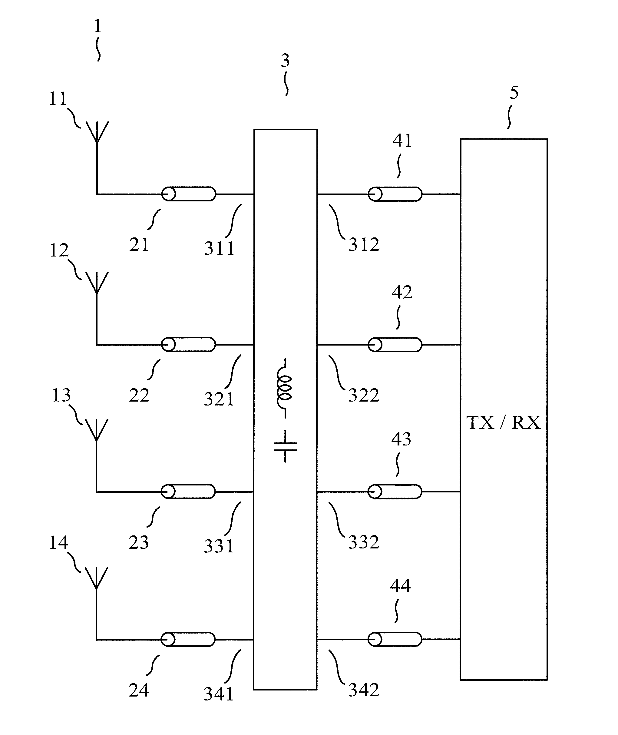
[0096]As a third embodiment of an apparatus of the invention, given by way of non-limiting example and best mode of carrying out the invention, we have represented in FIG. 6 an antenna tuning apparatus for a multiport antenna array, comprising:[0097]n=4 antenna ports (311) (321) (331) (341), each of the antenna ports being single-ended;[0098]m=4 user ports (312) (322) (332) (342), each of the user ports being single-ended;[0099]n adjustable impedance devices (301) each presenting a negative reactance and each being coupled in parallel with one of the antenna ports;[0100]n(n−1) / 2 adjustable impedance devices (302) each presenting a negative reactance and each having a first terminal coupled to one of the antenna ports and a second terminal coupled to one of the antenna ports which is different from the antenna port to which the first terminal is coupled;[0101]n=m windings (303) each having a first terminal coupled to one of the antenna ports and a second terminal coupled to...
PUM
 Abstract
Description
Claims
Application Information
 - R&D
- Intellectual Property
- Life Sciences
- Materials
- Tech Scout
- Unparalleled Data Quality
- Higher Quality Content
- 60% Fewer Hallucinations
Browse by: Latest US Patents, China's latest patents, Technical Efficacy Thesaurus, Application Domain, Technology Topic, Popular Technical Reports.
© 2025 PatSnap. All rights reserved.Legal|Privacy policy|Modern Slavery Act Transparency Statement|Sitemap|About US| Contact US: help@patsnap.com


