Numerically-controlled machine tool and spindle error compensating method thereof

a technology of numerical control and machine tools, applied in the direction of electric programme control, program control, instruments, etc., can solve problems such as defective machining

Active Publication Date: 2014-10-02
FANUC LTD
View PDF2 Cites 24 Cited by
  • Summary
  • Abstract
  • Description
  • Claims
  • Application Information

AI Technical Summary

Benefits of technology

The present invention provides a numerically-controlled machine tool with a spindle fixed to a linear moving axis and a table with multiple linear moving axes. The machine tool also includes a rotary table for fixing the workpiece and multiple rotary axes. The machine tool has a numerical controller that can compensate for errors in the spindle caused by assembly errors or deformation during machining. The spindle error compensating method can be provided for the numerically-controlled machine tool.

Problems solved by technology

However, when the workpiece is to be machined by being attached to the machine tool by using a jig such as a stock vice or a chuck, it is likely that the machining surface is inclined with respect to the moving axis and cannot be necessarily perpendicular or parallel, and manual fine adjustment is needed each time.
However, the technology disclosed in Japanese Patent Application Laid-Open No. 2010-201581 is only to compensate inclination of the workpiece, and if the spindle holding a machining tool is installed perpendicularly or parallelly with high accuracy with respect to the table on which the workpiece is placed, highly accurate machining is possible as illustrated in FIGS. 16A and 16B, but if the spindle is not installed perpendicular to or parallel to the table, it causes occurrence of defective machining such as a step in milling as illustrated in FIGS. 17A, 17B, and 17C and deformation of a drill in drilling.

Method used


Image

  • Numerically-controlled machine tool and spindle error compensating method thereof
  • Numerically-controlled machine tool and spindle error compensating method thereof
  • Numerically-controlled machine tool and spindle error compensating method thereof

Examples


Embodiment Construction

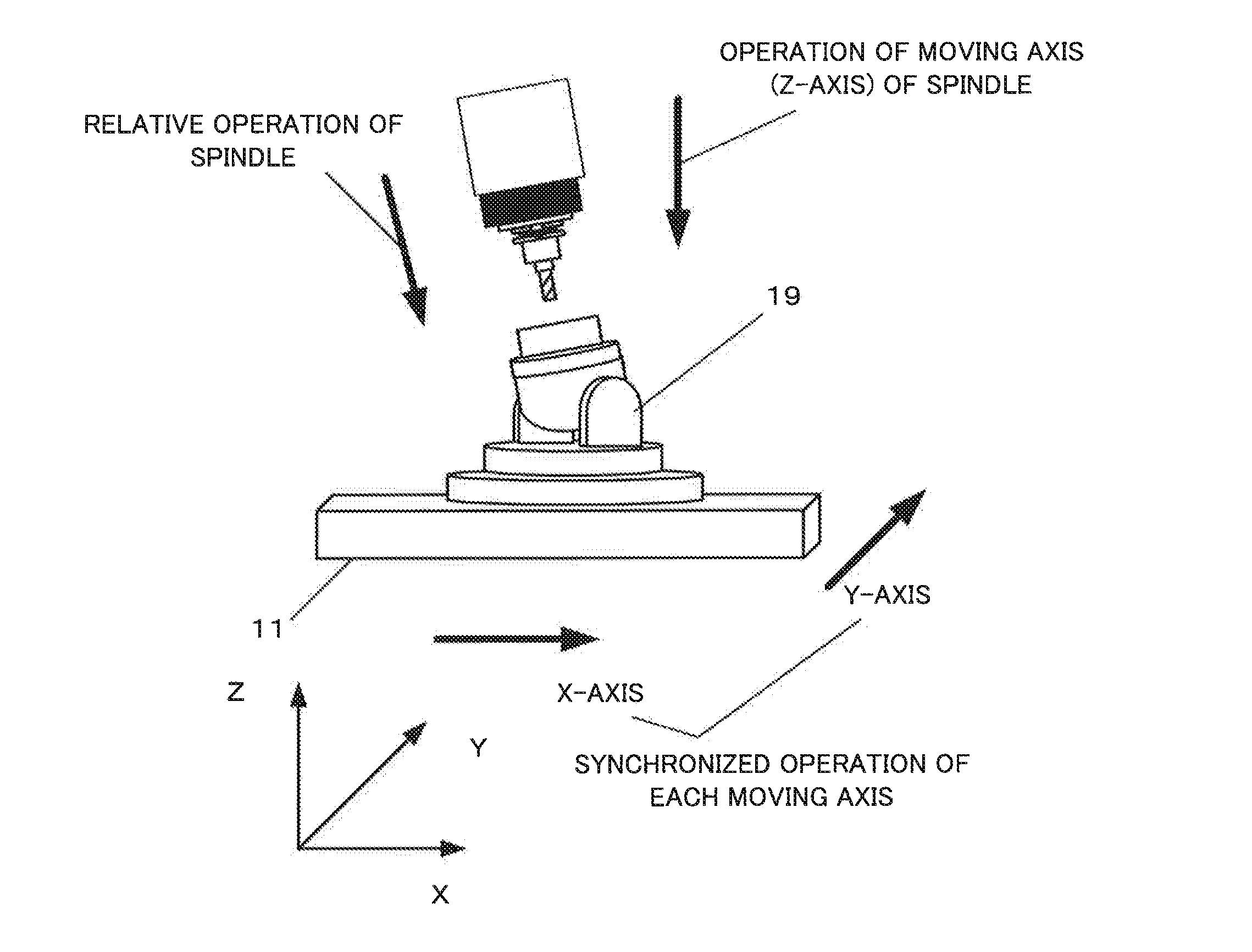
[0036]The present invention relates to a numerically-controlled machine tool provided with a spindle fixed to a linear moving axis, a table having two or more linear moving axes, and a rotary table for fixing a workpiece, installed on the table and having two or more rotary axes and also provided with a numerical controller for controlling the spindle and the table. This numerically-controlled machine tool employs the following embodiment in order to solve problems of an assembling error of the spindle fixed to the moving axis during a manufacturing stage of a machine tool main body and an error due to displacement of the spindle caused by deformation by heat generated during machining.

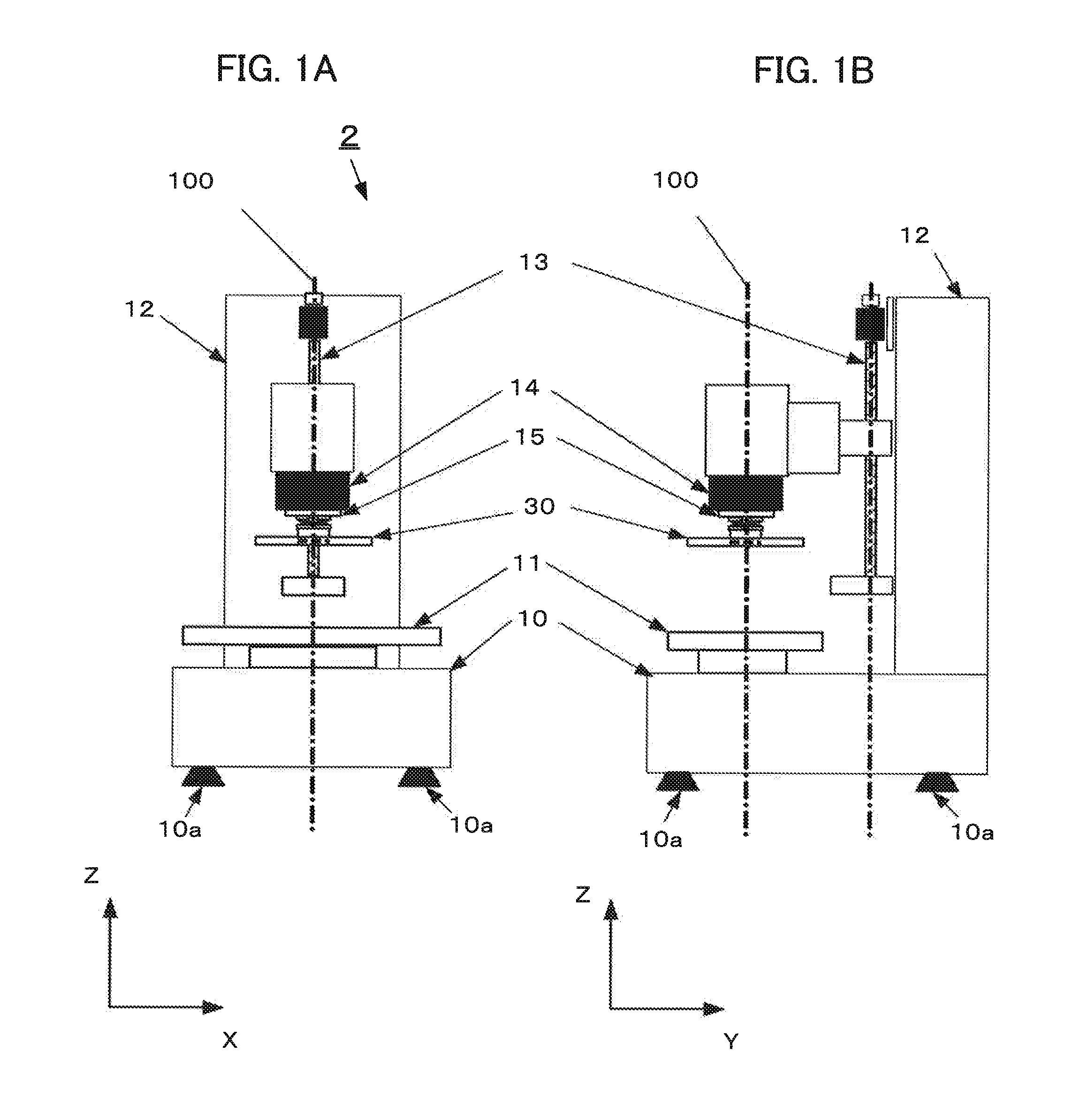
[0037]The machine tool will be described by using FIG. 1.

[0038]The machine tool 1 includes a machine tool main body 2 and a numerical controller 3 (see FIG. 9) controlling the machine tool main body 2. First, the machine tool main body 2 will be described. A bed 10 is formed having a substantially rec...


PUM


Abstract

A spindle error measurement jig is attached to a spindle of a numerically-controlled machine tool. A probe capable of measurement in a moving axis direction of each axis of the machine tool is installed on a table. By means of driving-control of a linear shaft driving the table and a linear shaft elevating a spindle head, spindle error measurement is made by measuring a spindle center position measurement hole and a spindle angular deviation measurement end-face so as to make spindle error calculation. On the basis of the calculation result, an angular deviation and a spindle error compensation amount are acquired, and they are used as parameters for compensating relative movement amounts of the table and the spindle so as to correct the spindle error.

Description

BACKGROUND OF THE INVENTION[0001]1. Field of the Invention[0002]The present invention relates to a numerically-controlled machine tool provided with a spindle error compensation function and the spindle error compensating method for the numerically-controlled machine tool.[0003]2. Description of the Related Art[0004]In a machine tool provided with a spindle fixed to a linear moving axis or a rotary axis and a table having one or more linear moving axes or rotary axes and also provided with a numerical controller for controlling an operation of the spindle and the table, when a vertical or parallel machining is to be performed on a machining surface of a workpiece with high accuracy, highly accurate working can be realized by installing the workpiece or the machining surface perpendicularly or parallelly with accuracy with respect to the moving axis.[0005]However, when the workpiece is to be machined by being attached to the machine tool by using a jig such as a stock vice or a chuck...

Claims


Application Information

Patent Timeline
Patent Type & Authority Applications(United States)
IPC IPC(8): G05B19/18
CPCG05B19/182G05B19/404G05B2219/50297
Inventor UENISHI, DAISUKE
Owner FANUC LTD
Why Eureka
Try Eureka