
Optical OFDM transmission

a transmission and optical technology, applied in the field of optical communication systems, can solve the problems of reducing the available osnr, excessive distortion, and the ultimate limit of the transmission capacity and/or reach, and achieve the effect of improving the nonlinear propagation performance of the transmitted signal

Active Publication Date: 2014-10-02
MONASH UNIV
View PDF5 Cites 20 Cited by
  • Summary
  • Abstract
  • Description
  • Claims
  • Application Information

AI Technical Summary

Benefits of technology

The present invention provides a method for transmitting digital information through a nonlinear optical channel using a combination of transmission parameters that improve the performance of the nonlinear propagation. The method involves generating an optical signal with a combination of subcarriers, symbol rate, and bits per symbol that provide an improvement in signal quality compared to conventional methods. The optical signal is then transmitted through the nonlinear optical channel and received by an optical receiver. The quality of the received signal is measured and the transmission parameters are determined to optimize the signal quality. The invention also provides an optical transmitter adapted for transmission of digital information through a nonlinear optical channel.

Problems solved by technology

As a result, the ultimate limit of transmission capacity and / or reach is generally nonlinear propagation effects, such as cross-phase modulation (XPM) in single-mode optical fibres.
Amplifying the transmitted signals to ever-higher power levels results in excessive distortion due to optical nonlinearities.
To avoid this, transmitted signal power must be limited, which reduces the available OSNR.
The inverse model technique is, however, highly computationally intensive.
As a result, it is impractical to perform the necessary pre-compensation or post-compensation in real-time on a live optical transmission link.
All such approaches are, however, necessarily approximations to a full compensation calculation, and therefore achieve imperfect results.

Method used


Image

  • Optical OFDM transmission
  • Optical OFDM transmission
  • Optical OFDM transmission

Examples


Embodiment Construction

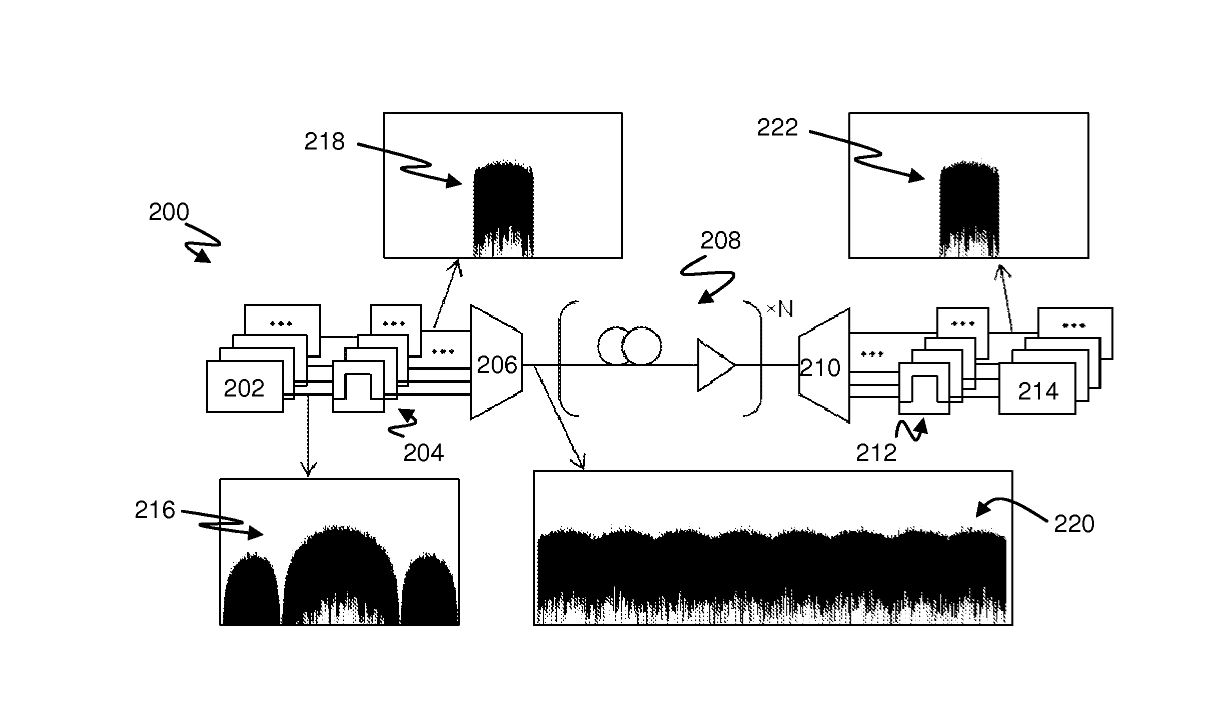
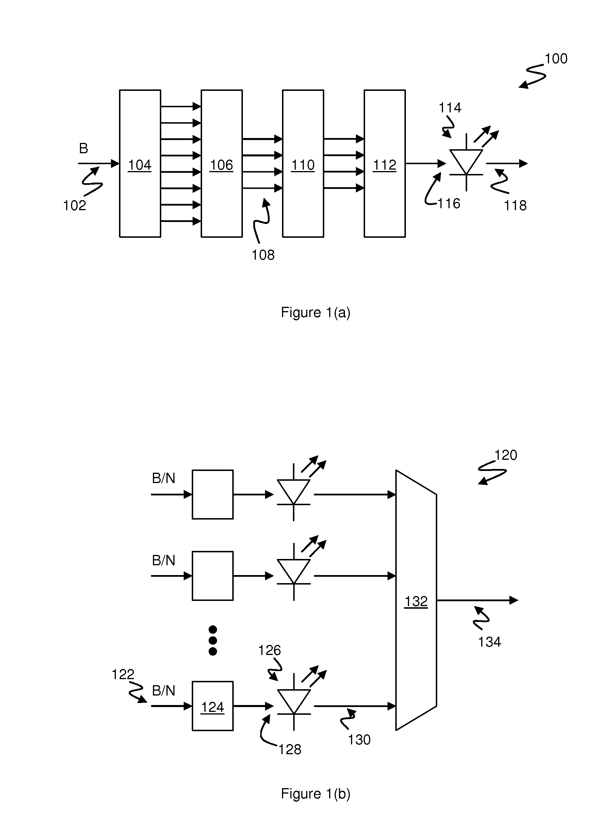
[0045]FIG. 1(a) is a block diagram illustrating an optical transmitter 100 according to one embodiment of the invention.

[0046]The transmitter 100 receives as input a serial information signal 102 having a predetermined bit-rate B, and comprises a multiplexed signal generator including a serial-to-parallel converter 104, a subcarrier modulator 106, a frequency-time transformer 110 and a multiplexed output processor 112.

[0047]The serial-to-parallel converter 104 provides a block of parallel digital inputs to the subcarrier modulator 106, which comprises a plurality of mapping units for generating a corresponding plurality of data symbols, each of which is generally a complex value encoding a number (b) of the input information bits 102. In general, each data symbol may encode more than one information bit, so that the number (N) of outputs 108 from the subcarrier modulator 106 is less than the number of parallel bit inputs. Symbols are generated at the outputs 108 at a symbol rate (S)...


PUM


Abstract

A method for transmitting digital information having a predetermined bit-rate (B) via a nonlinear optical channel includes determining a combination of transmission parameters comprising a number (N) of subcarriers, an information symbol rate (S) for each subcarrier, and a number (b) of bits per symbol on each subcarrier, such that B=NSb. An optical signal is generated comprising the plurality (N) of orthogonal optical subcarriers. Each subcarrier is modulated to carry a proportion (Sb / B) of the total bit-rate (B) of the digital information. The optical signal is then transmitted to a corresponding optical receiver via the nonlinear optical channel. The received signal has a measurable signal quality (Q) which is a function of the transmission parameters (N, S, b). Determining the combination of transmission parameters comprises selecting the parameters such that the associated signal quality is greater than a corresponding quality for a single-carrier transmission, and greater than a corresponding quality employing a larger number (M>N) of subcarriers.

Description

FIELD OF THE INVENTION[0001]The present invention relates to optical communications systems, and more particularly to improvements in high-density Optical Frequency Division Multiplexed or Wavelength Division Multiplexed transmission.BACKGROUND OF THE INVENTION[0002]The maximum capacity and / or transmission distance in optical fibre communications links is no longer limited primarily by linear processes, such as chromatic dispersion and polarisation mode dispersion (PMD), or by additive noise. A variety of optical and electronic technologies are available, for use in incoherent and coherent communications links, which are able to fully compensate for linear dispersion effects. In addition, efficient and cost-effective optical amplification technologies, such as Erbium-Doped Fibre Amplifiers (EDFAs) are able to boost transmitted signal power in order to maintain an adequate Optical Signal-to-Noise Ratio (OSNR) for reliable recovery of the transmitted information.[0003]As a result, the...

Claims


Application Information

Patent Timeline
IPC IPC(8): H04J14/02H04L27/26H04B10/2575H04B10/548
CPCH04J14/0298H04L27/2601H04B10/2575H04B10/548H04L5/0007H04L5/0046
Inventor LOWERY, ARTHUR JAMESDU, LIANG BANGYUAN
Owner MONASH UNIV
Learn More