
Optical disc device and optical disc determination method

Active Publication Date: 2014-10-02
JVC KENWOOD CORP A CORP OF JAPAN
View PDF9 Cites 0 Cited by
  • Summary
  • Abstract
  • Description
  • Claims
  • Application Information

AI Technical Summary

Benefits of technology

The purpose of the patent is to create an optical disc device and method that can easily identify high-density optical discs.

Problems solved by technology

In this way, such a conventional optical disc device has a problem that it is not easy to determine a high-density optical disc.

Method used


Image

  • Optical disc device and optical disc determination method
  • Optical disc device and optical disc determination method
  • Optical disc device and optical disc determination method

Examples


Embodiment Construction

[Configuration of Optical Disc Device]

[0014]A description is made below, in detail, of an optical disc device according to the embodiments by using the drawings. It should be noted that, unless specifically described, constituents, types, combinations, shapes, relative arrangements thereof, and the like, which are described in the present embodiments, are not intended to limit the scope of the invention only thereto and are nothing more than mere explanatory examples. Moreover, the same reference symbols and numerals are assigned to the same portions and items as those already described and a duplicate description is omitted.

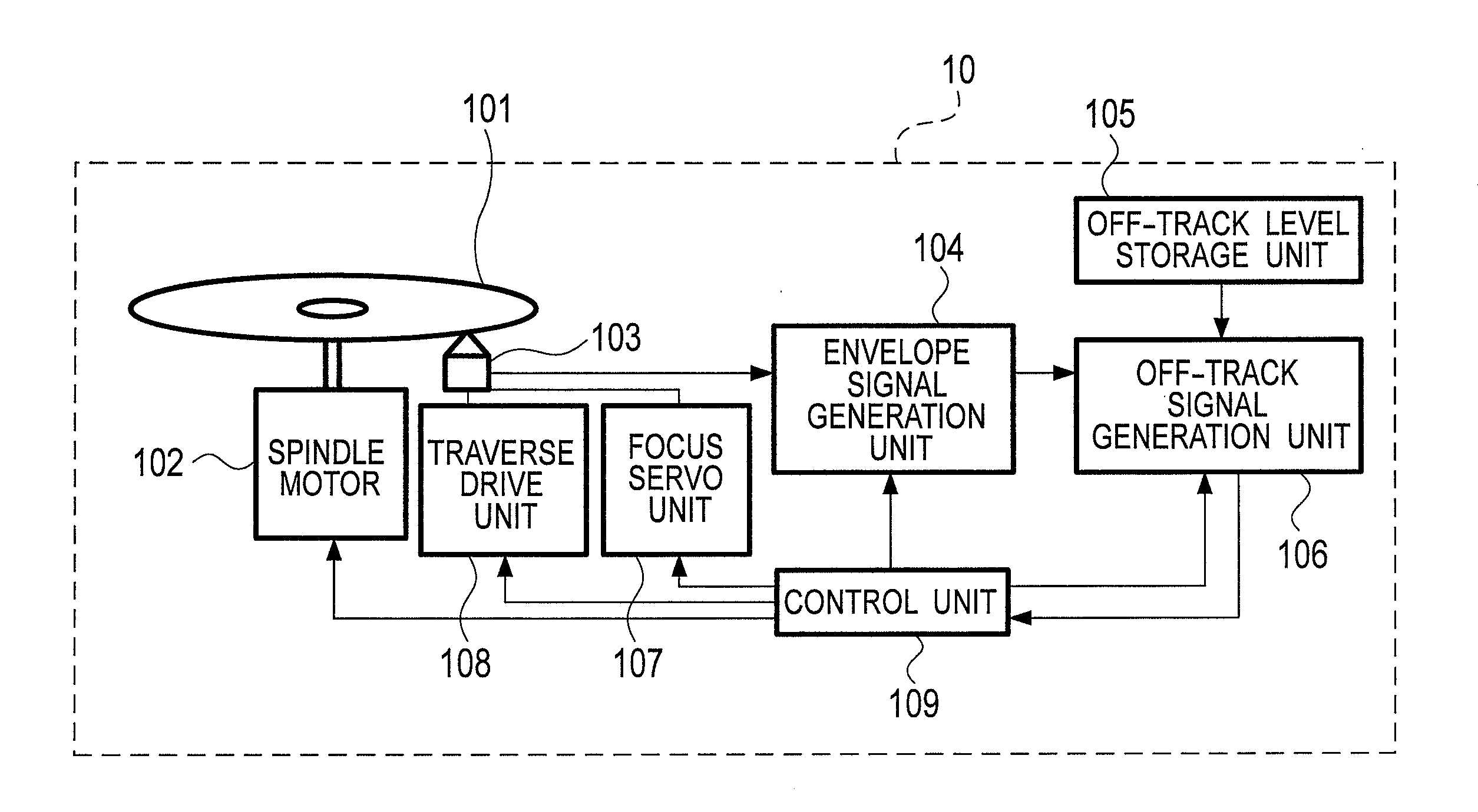
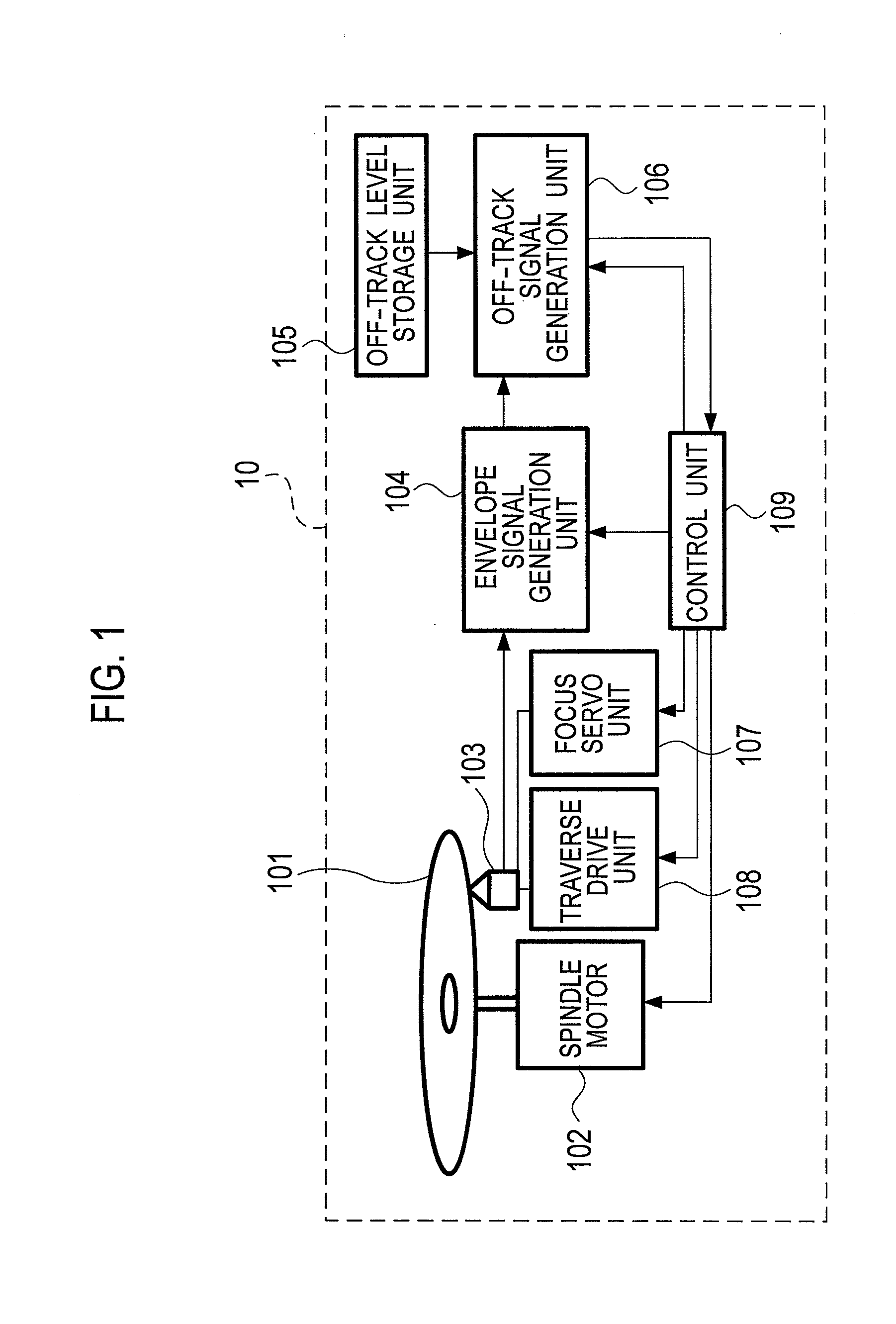
[0015]FIG. 1 is a block configuration diagram showing a configuration of the optical disc device according to the embodiments.

[0016]In FIG. 1, a spindle motor 102 of an optical disc device 10 rotates an optical disc 101. An optical pickup 103 radiates a laser beam onto the optical disc 101, receives reflected light therefrom, and generates an RF signal. An envel...


PUM


Abstract

An optical pickup of an optical disc device is configured to read a signal recorded in an optical disc. An envelope signal generation unit is configured to generate an envelope signal from the signal read by the optical pickup. An off-track level storage unit stores an off-track level. An off-track signal generation unit is configured to generate an off-track signal by binarizing the envelope signal, which is generated by the envelope signal generation unit, using the off-track level stored by the off-track level storage unit. A determination unit is configured to output a disc determination signal, which indicates whether the optical disc is a standard-density optical disc or a high-density optical disc in which a line density is higher than the standard density, based on the off-track signal generated by the off-track signal generation unit.

Description

CROSS REFERENCE TO RELATED APPLICATION[0001]This application is based upon and claims the benefit of priority under 35 U.S.C. §119 from Japanese Patent Application No. 2013-072317, filed on Mar. 29, 2013, the entire contents of which are incorporated herein by reference.BACKGROUND[0002]The embodiments relate to an optical disc device and an optical disc determination method, which determine whether an optical disc is a standard-density optical disc or a high-density optical disc in which line density is higher than standard density.[0003]There is known a high-density optical disc, in which, in order to increase recording density without changing the recording format of the optical disc to a large extent, line density is increased by narrowing the track pitch, shortening the shortest length of the recording pit, and so on.[0004]For example, the storage capacity of a CD-R as specified in the Orange Book specification is up to 700 MB (80 minutes for music); however, a CD-R with high-de...

Claims


Application Information

Patent Timeline
IPC IPC(8): G11B19/12G11B7/24094
CPCG11B7/24094G11B19/128
Inventor ARAI, TSUTOMU
Owner JVC KENWOOD CORP A CORP OF JAPAN
Learn More