
Image pickup apparatus

a technology of image pickup and image, which is applied in the direction of direction/deviation determining electromagnetic systems, instruments, television systems, etc., can solve the problems of inability of photometric sensors to capture high-resolution object images, sometimes out of focus of object images formed on focusing screens, and inability of photometric sensors to capture objects with high resolution. achieve the effect of performing object recognition with accuracy

Inactive Publication Date: 2014-10-02
CANON KK
View PDF2 Cites 4 Cited by
  • Summary
  • Abstract
  • Description
  • Claims
  • Application Information

AI Technical Summary

Benefits of technology

The present invention is an image pickup apparatus that can accurately recognize objects even when the object is out of focus on a photometric sensor. This means that the apparatus can capture the object image with high resolution, ensuring accurate object recognition.

Problems solved by technology

However, due to defocusing of a photographing lens caused by a focus detection error and / or due to environmental factors (such as a position adjustment deviation of the photometric sensor and deformations of components of a photometric system under a high temperature and high humidity environment), an object image formed on the focusing screen sometimes becomes out of focus on the photometric sensor.
In that case, it becomes impossible for the photometric sensor to capture, with high resolution, the object image formed on the focusing screen.
H05-053043, if an object image formed on the focusing screen becomes out of focus on the photometric sensor due to various factors described above, the photometric sensor cannot capture with high resolution the object image.
This makes it difficult to perform highly accurate object recognition.

Method used


Image

  • Image pickup apparatus
  • Image pickup apparatus
  • Image pickup apparatus

Examples


first embodiment

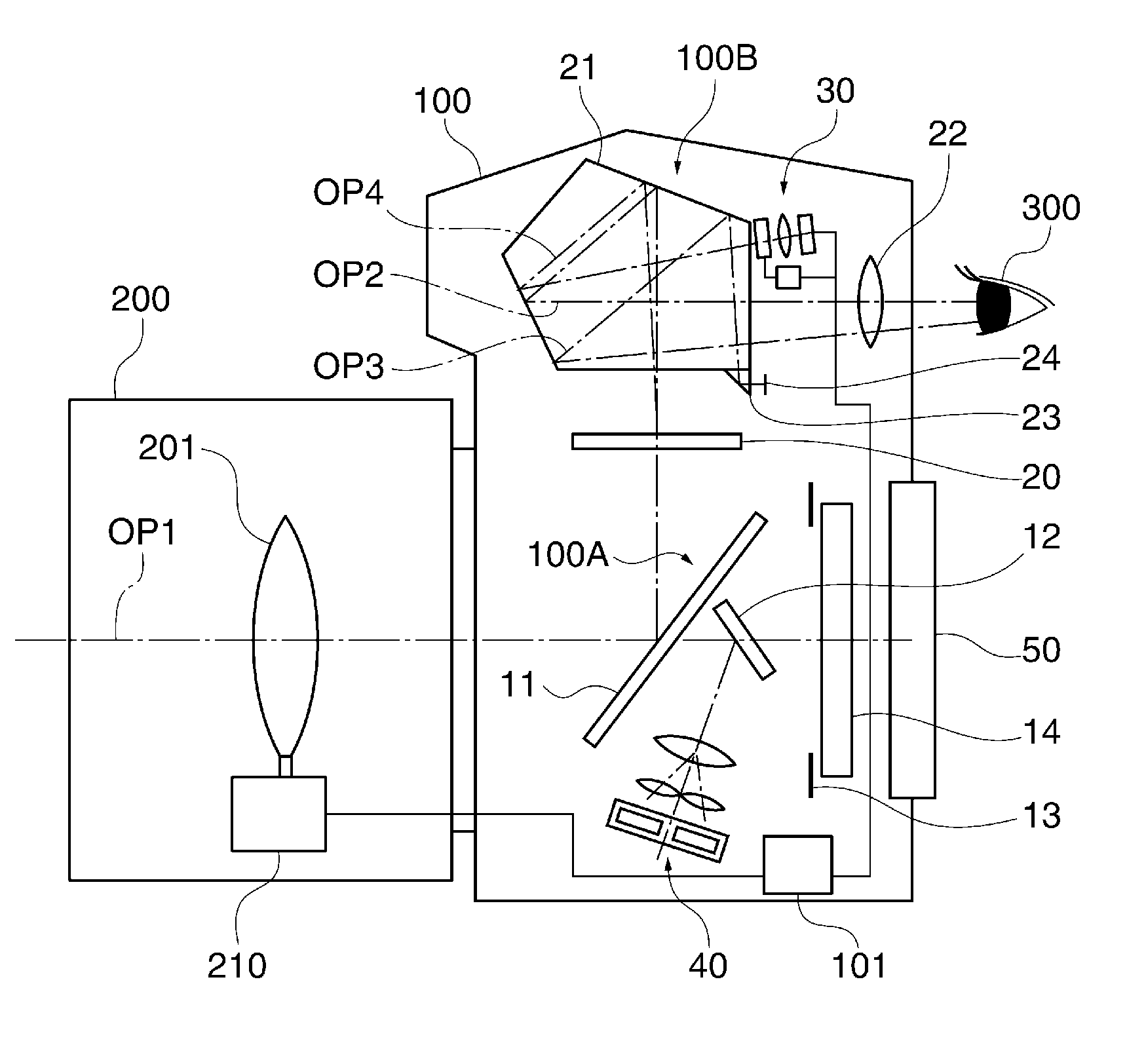
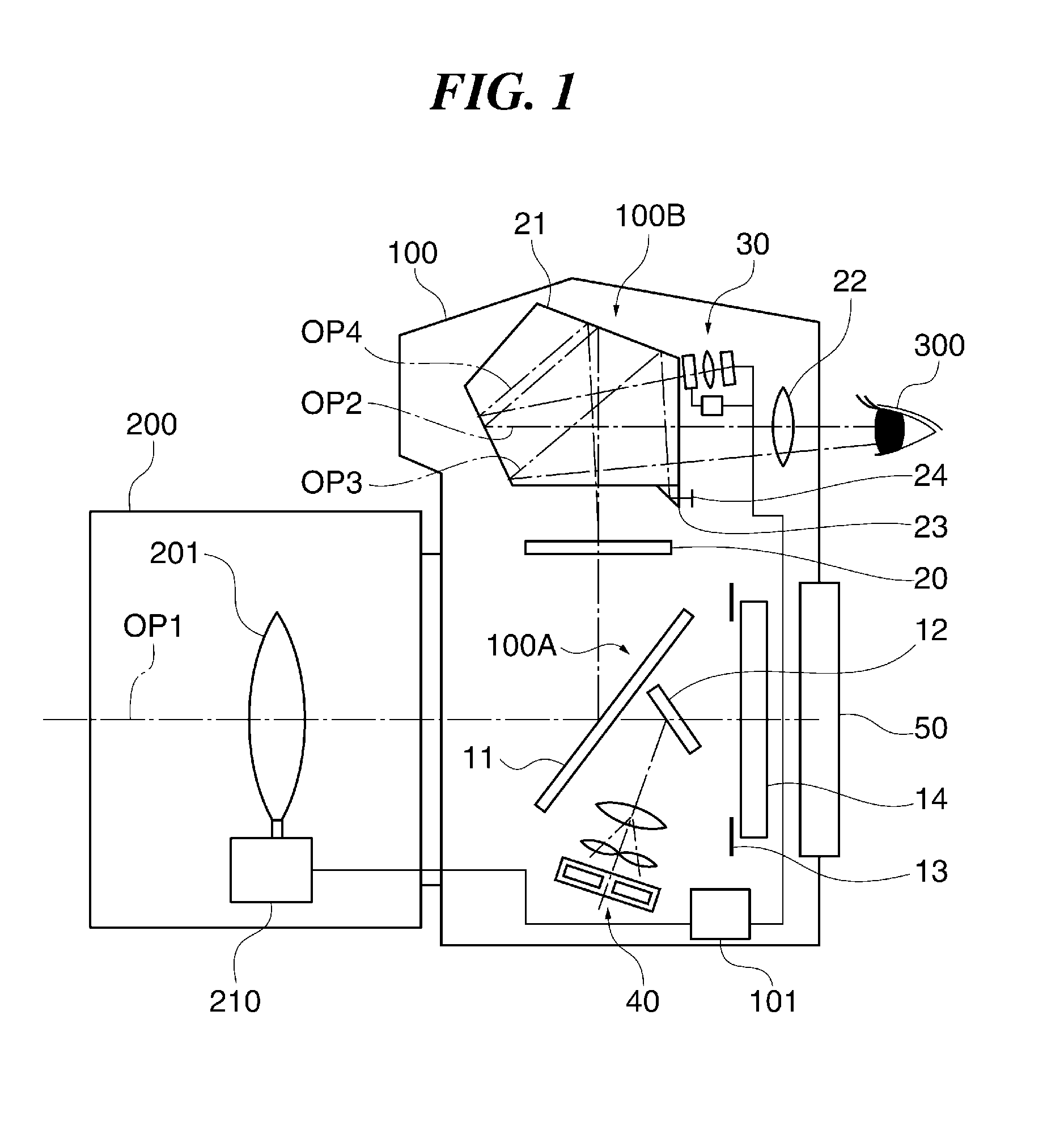
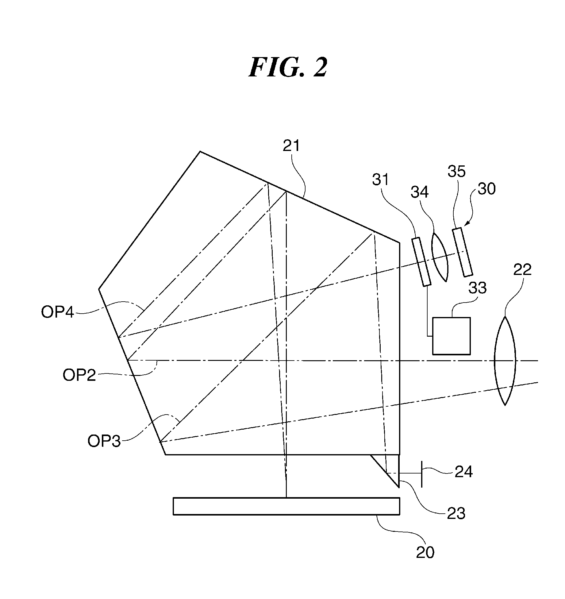
[0028]FIG. 1 schematically shows in section view a digital single-lens reflex camera that is first embodiment of an image pickup apparatus according to this invention, and FIG. 2 shows an example construction of a photometric device mounted to the digital single-lens reflex camera.

[0029]As shown in FIG. 1, the digital single-lens reflex camera (hereinafter, sometimes referred to as the camera) of this embodiment has a camera main unit 100 and a lens barrel 200 replaceably attached to the camera main unit 100. The camera main unit 100 has a mirror mechanism 100A, a finder optical system 100B, a photometric device 30, a focus detection device 40, a display device 50, a focal-plane shutter 13, an imaging element 14 (such as a CCD sensor or a CMOS sensor), a CPU 101, and the like. The lens barrel 200 has a lens group 201 for performing focusing and zooming, a lens driving device 210 for driving the lens group 201, an aperture device (not shown), etc.

[0030]The mirror mechanism 100A has a...

second embodiment

[0099]In the following, a description will be given of a digital single-lens reflex camera, which is an image pickup apparatus of a second embodiment of this invention. The camera of this embodiment is basically the same as that of the first embodiment, and a description of points common to these two embodiments will be omitted.

[0100]FIG. 11 shows in flowchart an essential part of operation (i.e., processing relating to object recognition and aperture value control process) of the camera of this embodiment.

[0101]The CPU 101 sequentially executes processing in steps S200-S203 of FIG. 8A. More specifically, the CPU 101 performs the initialization processing when the power is on, causes the focus detection device 40 to make a focus detection when the switch SW1 of the release switch 80 is on, and causes the lens driving device 210 to drive the lens group 201 according to an output signal of the focus detection device 40 to achieve focusing. Then, in step S204 corresponding to step S204...


PUM


Abstract

An image pickup apparatus capable of performing object recognition with accuracy even when an object image formed on a focusing screen becomes out of focus on a photometric sensor. A light flux of the object image formed on the focusing screen is captured by the photometric sensor through a variable photometric aperture, and object recognition is performed by an object recognition unit based on image information contained in photometric information output from the photometric sensor. If determined that the object recognition cannot be achieved based on an object recognition operation of the object recognition unit performed according to the image information, the variable photometric aperture is stopped down under the control of a photometric control unit.

Description

BACKGROUND OF THE INVENTION[0001]1. Field of the Invention[0002]The present invention relates to an image pickup apparatus capable of performing object recognition.[0003]2. Description of the Related Art[0004]In an image pickup apparatus such as a digital single-lens reflex camera, an object image formed on a focusing screen is captured by a photometric sensor (which is disposed near a pentagonal prism) via a photometric aperture and a photometric lens, and a brightness of the object image is measured by the photometric sensor to decide a proper exposure. It is also known to recognize a main object from an object image captured by the photometric sensor.[0005]With regard to the object recognition, an object recognition device has been proposed that recognizes as amain object an object gazed through a view finder, and tracks the object based on information about a color or brightness of an image of the main object (see, Japanese Laid-open Patent Publication No. H05-053043).[0006]To p...

Claims


Application Information

Patent Timeline
IPC IPC(8): G01S3/786G06V10/141
CPCG01S3/7864G02B17/04G06V40/10G06V10/141H04N23/61H04N23/71H04N23/73
Inventor KIMURA, TETSUYA
Owner CANON KK
Learn More