
Vascular plaque removal systems, devices, and methods

a technology of vascular plaque and removal system, which is applied in the field of systems, devices and methods for treating stenosis of blood vessels, can solve the problems of thrombosis (i.e., blood clot formation) and partial or total occlusion of those blood vessels

Inactive Publication Date: 2014-09-18
STINIS CURTISS T
View PDF4 Cites 33 Cited by
  • Summary
  • Abstract
  • Description
  • Claims
  • Application Information

AI Technical Summary

Benefits of technology

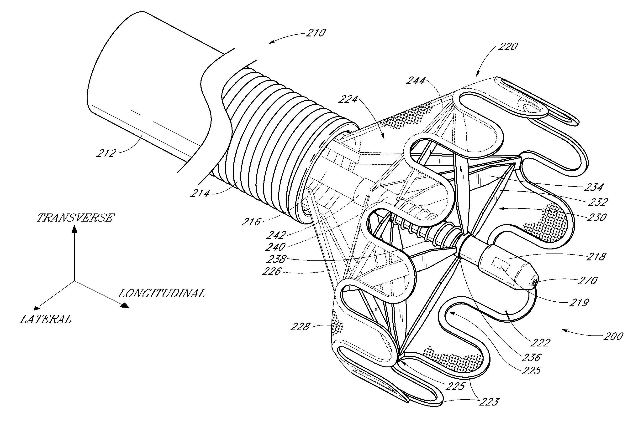
The patent describes a medical device that can be used to remove blockages in the blood vessels of a patient. The device includes a catheter with a dissection tip that can be expanded and contracted to fit different sizes of blood vessels. The dissection tip has projections that can cut up plaque or blood clots and is positioned between the plaque and the outer wall of the blood vessel. The device can be advanced through the patient's vasculature using a guidewire or without a guidewire. The dissection tip can be expanded and contracted to fit different sizes of blood vessels, and it can be designed to cut up plaque or blood clots within the receiving space of the device. The device can also be used to aspirate the plaque or blood clots from the patient's vasculature. The technical effects of the invention include improved blood flow, reduced plaque buildup, and improved treatment of vascular obstacles.

Problems solved by technology

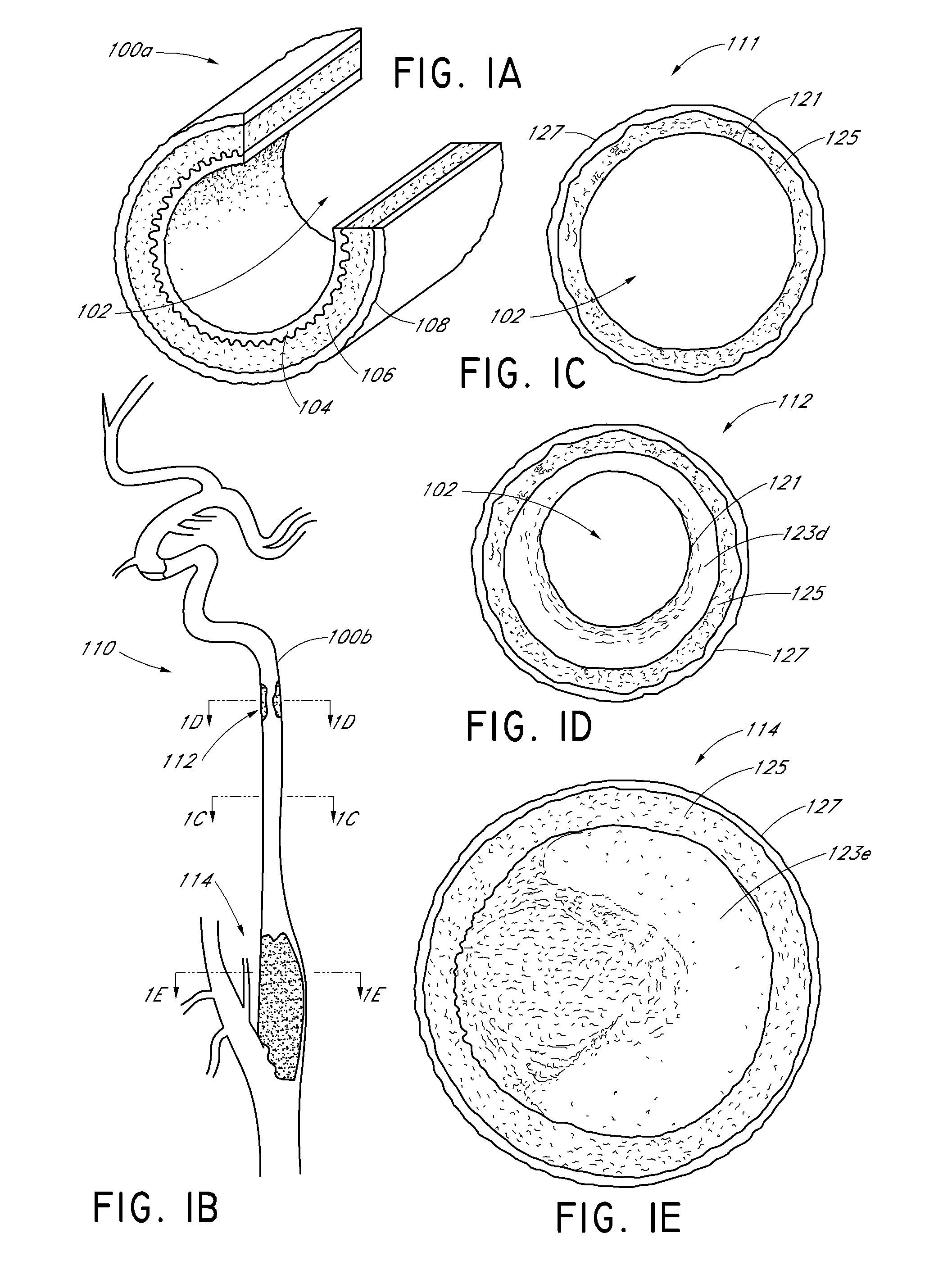
Over time, the accumulated plaque can result in stenosis, or the narrowing of one or more lumens within the patient's vasculature, resulting in a partial or total occlusion of those blood vessels.
The accumulated plaque can also crack or rupture and cause platelets to coagulate at the site of injury, leading to thrombus (i.e., blood clot) formation.

Method used


Image

  • Vascular plaque removal systems, devices, and methods
  • Vascular plaque removal systems, devices, and methods
  • Vascular plaque removal systems, devices, and methods

Examples


Embodiment Construction

,” one will understand how the features of the devices and methods disclosed herein provide advantages over other known devices and methods.

[0006]In one embodiment, a method may include, for example, introducing a medical article into a patient's vasculature. The medical article may include, for example, a radially adjustable dissection tip having projections extending along the edge of the dissection tip, a receiving space disposed proximal to the dissection tip, a casing layer disposed circumferentially around at least a portion of the dissection tip and defining the receiving space, and an aspiration lumen disposed proximal to the receiving space. The method may also include, for example, positioning the dissection tip between a volume of plaque tissue, a blood clot, or other vascular obstruction and an outer wall of the patient's vasculature. The method may further include receiving the volume of plaque tissue, the blood clot, or other obstructing material in the receiving space...


PUM


Abstract

Systems, devices, and methods for removing plaque from a patient's vasculature are disclosed. In one example, a medical article includes a catheter body and a dissection tip. The dissection tip can move between at least a first position and a second position and can be biased to expand radially from a longitudinal axis of the medical article when the dissection tip is moved from the first position to the second position. In one example, a dissection member includes a dissection tip, a receiving space, and a severing element, such as, for example a thrombus-breaking element. The dissection tip can radially adjust to circumferentially maneuver between a core of plaque or a blood clot and a patient's vasculature. The receiving space can receive the plaque or clot that passes within the dissection tip. The severing element can at least partially sever or break apart the plaque or clot.

Description

BACKGROUND[0001]1. Field of the Invention[0002]Embodiments disclosed herein relate generally to systems, devices, and methods for treating stenosed blood vessels. More specifically, certain embodiments concern systems, devices, and methods that can be implemented to perform an endovascular endarterectomy procedure in a patient to treat stenosis caused, at least in part, by atherosclerosis.[0003]2. Description of the Related Art[0004]Atherosclerosis can be caused by the accumulation of plaque (e.g., atherosclerotic tissue) inside a person's vasculature. Over time, the accumulated plaque can result in stenosis, or the narrowing of one or more lumens within the patient's vasculature, resulting in a partial or total occlusion of those blood vessels. The accumulated plaque can also crack or rupture and cause platelets to coagulate at the site of injury, leading to thrombus (i.e., blood clot) formation. Vessel occlusion and blood clot formation can each result in coronary artery disease, ...

Claims


Application Information

Patent Timeline
Patent Type & Authority Applications(United States)
IPC IPC(8): A61B17/3207A61B17/221
CPCA61B17/320725A61B17/320758A61B17/221A61B17/3207A61B2017/22094A61B2017/2215A61B2017/320064A61B2017/320775A61B2090/3784
Inventor STINIS, CURTISS T.
Owner STINIS CURTISS T
Learn More