Step-down circuit and power receiving device using step-down circuit

Inactive Publication Date: 2014-09-18
MURATA MFG CO LTD
View PDF2 Cites 0 Cited by
  • Summary
  • Abstract
  • Description
  • Claims
  • Application Information

AI Technical Summary

Benefits of technology

The present invention relates to a piezoelectric transformer for a power receiving device. The technical effects of this invention are as follows: 1) The piezoelectric transformer has a symmetric structure sandwiching the higher voltage portion between the two lower voltage portions and is driven with a vibration mode set to the 3 / 2λ or 5 / 2λ mode, which reduces adverse effects on mounted portions caused by the vibration mode and improves mounting stability; 2) The piezoelectric transformer can be supported at nodes of the vibration mode or the input electrode and output electrodes can be arranged at the nodes, which reduces stress and distortion caused by the vibration and improves power transfer efficiency and impedance matching with the load circuit; 3) The unbalance-balance conversion can be performed with one piezoelectric transformer, which simplifies the construction of the step-down circuit and allows for a smaller size and higher power-transfer efficiency of the power receiving device.

Problems solved by technology

Furthermore, since the unbalance-balance conversion can be performed with one piezoelectric transformer, it is easier to reduce the size and the thickness of the step-down circuit.

Method used


Image

  • Step-down circuit and power receiving device using step-down circuit
  • Step-down circuit and power receiving device using step-down circuit
  • Step-down circuit and power receiving device using step-down circuit

Examples


embodiment 1

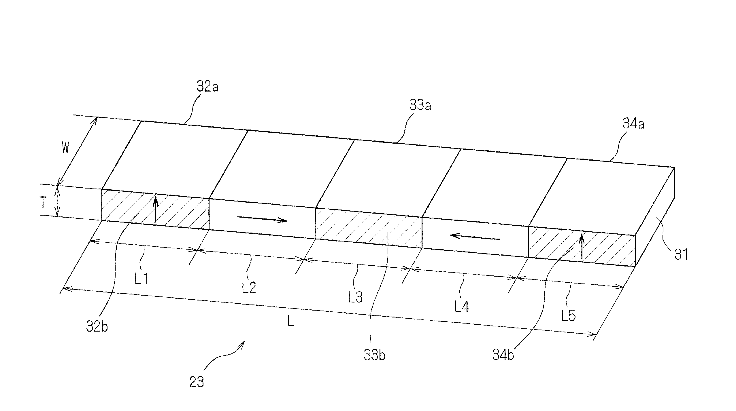
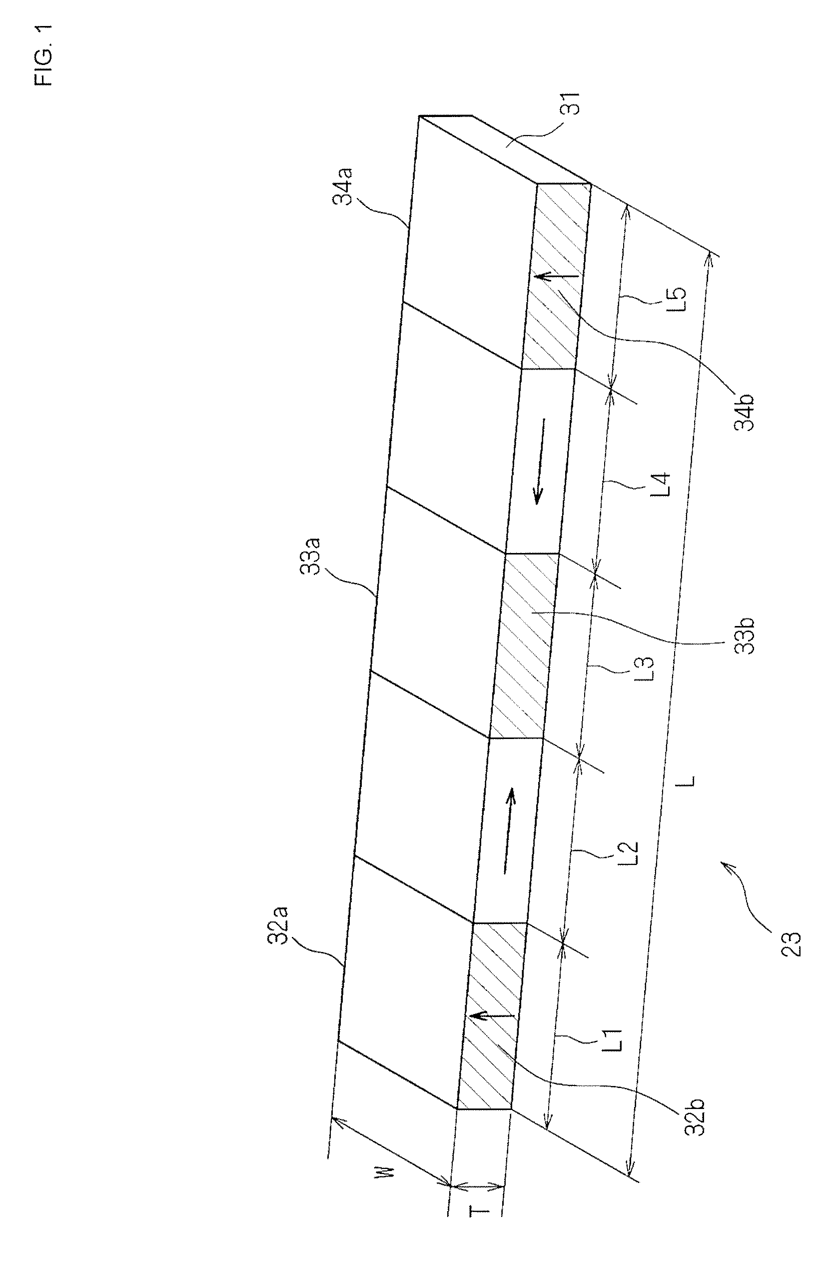
[0064]FIG. 1 is a perspective view illustrating the configuration of a piezoelectric transformer of 5 / 2λ mode type, which is used in a step-down circuit according to Embodiment 1 of the present invention. As illustrated in FIG. 1, a piezoelectric transformer 23 according to Embodiment 1 is formed of a piezoelectric plate 31 that is a piezoelectric ceramic multilayer plate having a rectangular parallelepiped shape with a thickness T, a width W, and a length L. Opposite end portions of the piezoelectric plate 31 are lower voltage portions L1 and L5 each exhibiting a comparatively low voltage, and a central portion of the piezoelectric plate 31 is a higher voltage portion L3 exhibiting a comparatively high voltage. The piezoelectric transformer 23 is a piezoelectric transformer having a symmetric structure and driven in the 5 / 2λ mode. Output electrodes 34a and 34b are formed in one lower voltage portion L5 of the piezoelectric transformer 23, input electrodes 33a and 33b are formed in ...

embodiment 2

[0085]A piezoelectric transformer of 5 / 2λ mode type used in a step-down circuit according to Embodiment 2 has a similar configuration to that in Embodiment 1. Therefore, corresponding components of the power transfer circuit are denoted by the same reference signs, and detailed description of those components is omitted. Embodiment 2 is different from Embodiment 1 in that the lower voltage portions L1 and L5 are polarized in the direction of the thickness T of the piezoelectric plate 31 (i.e., in the direction perpendicular to the lengthwise direction of the piezoelectric plate 31) and further in directions opposite to each other. FIG. 8 is a schematic view illustrating a polarized state of the piezoelectric transformer 23 according to Embodiment 2 of the present invention.

[0086]As illustrated in FIG. 8, the lower voltage portions L1 and L5 are polarized in the direction of the thickness T of the piezoelectric plate 31 and further in directions opposite to each other. The polarized ...

embodiment 3

[0092]A piezoelectric transformer of 5 / 2λ mode type used in a step-down circuit according to Embodiment 3 of the present invention has a similar configuration to those in Embodiments 1 and 2. Therefore, corresponding components of the power transfer circuit are denoted by the same reference signs, and detailed description of these components is omitted. Embodiment 3 is different from Embodiments 1 and 2 in that the lower voltage portions L1 and L5 are polarized in the lengthwise direction of the piezoelectric plate 31.

[0093]FIG. 10 is a perspective view illustrating the configuration of the piezoelectric transformer 23 of 5 / 2λ mode type, which is used in a step-down circuit according to Embodiment 3 of the present invention. As illustrated in FIG. 10, the piezoelectric transformer 23 according to Embodiment 3 is formed of a piezoelectric plate 31 that is a piezoelectric ceramic multilayer plate having a rectangular parallelepiped shape with a thickness T, a width W, and a length L. ...


PUM


Abstract

A step-down circuit using a piezoelectric transformer that includes a rectangular parallelepiped piezoelectric plate having opposite end portions in a lengthwise direction thereof, which are constituted as two lower voltage portions provided with output electrodes, and a region sandwiched between the two lower voltage portions. The region being partly constituted as a higher voltage portion provided with an input electrode. The two lower voltage portions and the higher voltage portion are each polarized and driven in a 3 / 2λ or a 5 / 2λ mode. The higher voltage portion or vicinities thereof are polarized in directions symmetric to each other on both the sides of a center of the higher voltage portion or on both the sides of the higher voltage portion. The output electrodes on the positive and negative charge sides of respective polarized lower voltage portions are connected to each other.

Description

CROSS-REFERENCE TO RELATED APPLICATIONS[0001]The present application is a continuation of PCT / JP2012 / 075353 filed Oct. 1, 2012, which claims priority to Japanese Patent Application No. 2011-264076, filed Dec. 1, 2011, the entire contents of each of which are incorporated herein by reference.FIELD OF THE INVENTION[0002]The present invention relates to a step-down circuit, which has a simple structure and a lower height, and which can perform unbalance-balance conversion and voltage step-down at the same time, and further relates to a power receiving device using the step-down circuit.BACKGROUND OF THE INVENTION[0003]Various types of electronic equipment for transferring electric power in a non-contact manner have been developed in recent years. To transfer electric power with the electronic equipment in a non-contact manner, a power transfer system of magnetic field coupling type including coil modules in both a power transmitting unit and a power receiving unit is employed in many c...

Claims


Application Information

Patent Timeline
IPC IPC(8): H01L41/04H02J17/00H01L41/107H02M3/24
CPCH01L41/044H02J17/00H01L41/107H02M5/04H02J7/02H02J50/12H10N30/804H10N30/40H02J50/10
Inventor ICHIKAWA, KEIICHI
Owner MURATA MFG CO LTD
Why Eureka
Try Eureka