
Rotary Encoder with Free Floating Flexible Sensor Carrier

Active Publication Date: 2014-09-18
KIRK CHARLES R +1
View PDF21 Cites 9 Cited by
  • Summary
  • Abstract
  • Description
  • Claims
  • Application Information

AI Technical Summary

Benefits of technology

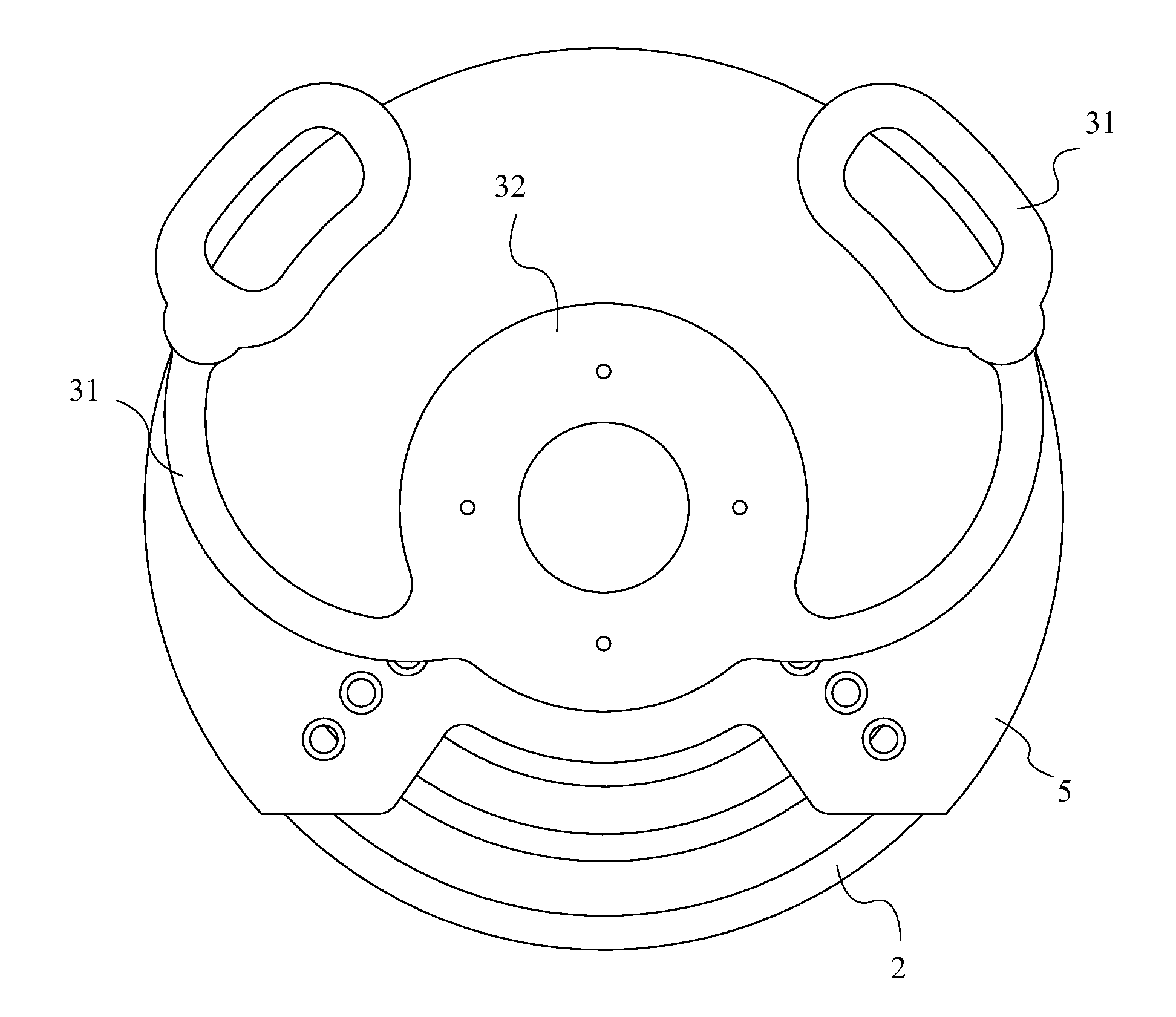
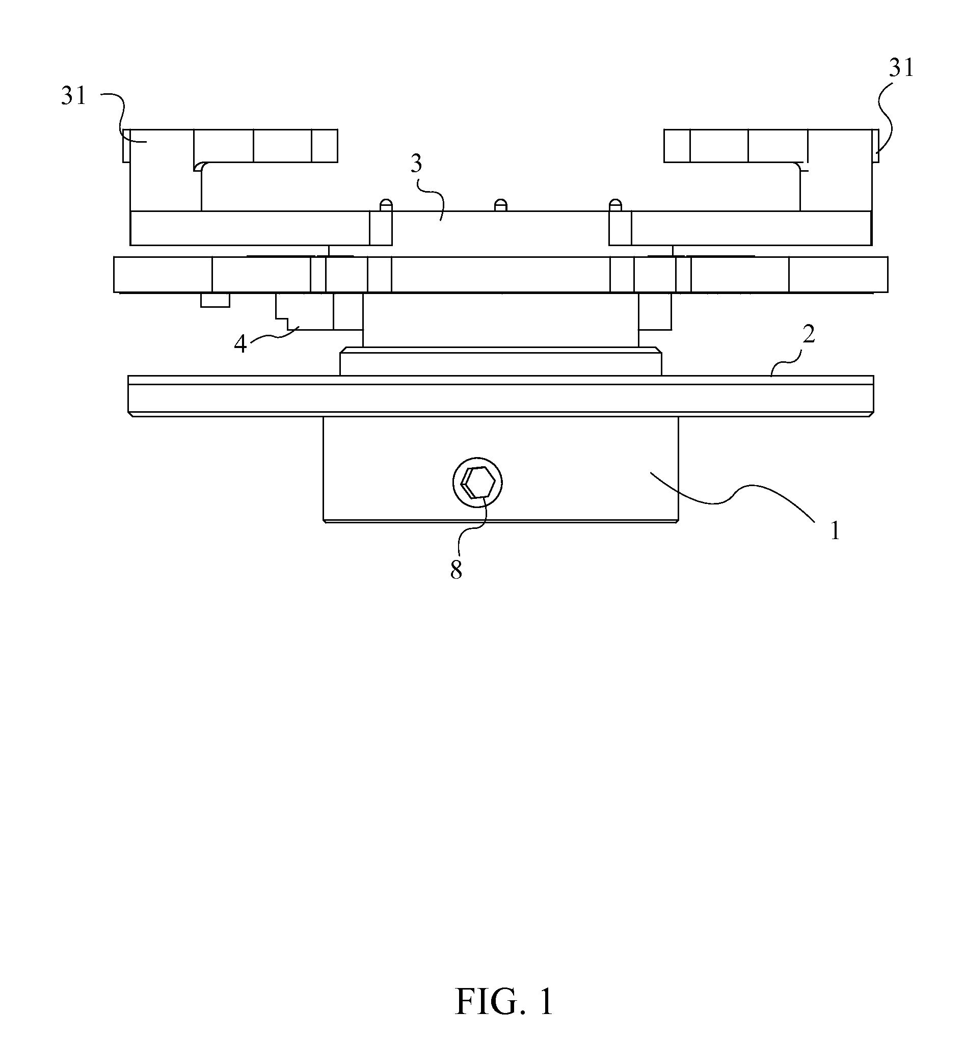
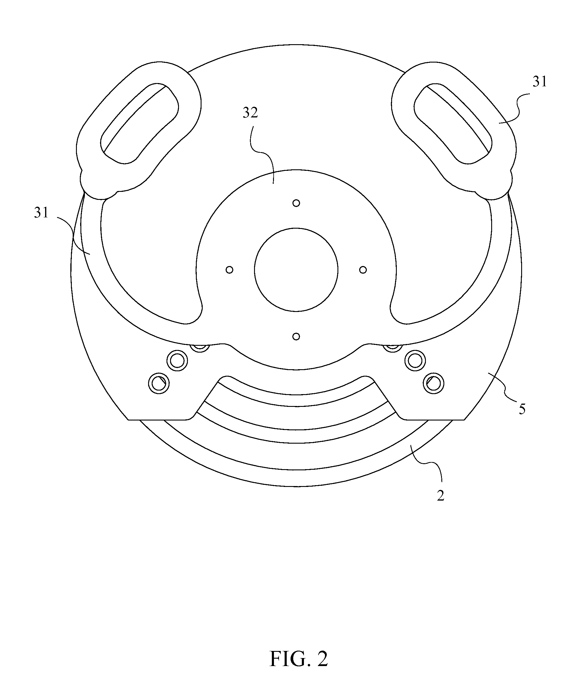
The present invention is an apparatus for an encoder that eliminates the need for ball bearings and flexible coupling. The invention uses a new and innovative method to bring the active elements of the encoder into alignment and holding that alignment at a minimum of cost. The invention also includes parts that are injection molded from advanced plastic compounds to further reduce cost, assembly labor, and improve overall performance and reliability. The invention provides a solution for those who need to measure and control the motion of shafts and axles in various applications such as industrial controls, robotics, elevators, escalators, and medical equipment. The invention also describes the design of a component that modifies the output of an encoder to improve its performance and reliability.

Problems solved by technology

The motor performs poorly or not at all if timing is not adjusted correctly.
Improper encoder alignment on the motor actually causes it to run backwards resulting in a hazardous run away condition.

Method used


Image

  • Rotary Encoder with Free Floating Flexible Sensor Carrier
  • Rotary Encoder with Free Floating Flexible Sensor Carrier
  • Rotary Encoder with Free Floating Flexible Sensor Carrier

Examples


Embodiment Construction

[0021]All illustrations of the drawings are for the purpose of describing selected versions of the present invention and are not intended to limit the scope of the present invention. The present invention is to be described in detail and is provided in a manner that establishes a thorough understanding of the present invention. There may be aspects of the present invention that may be practiced without the implementation of some features as they are described. It should be understood that some details have not been described in detail in order to not unnecessarily obscure focus of the invention.

[0022]The present invention is a rotary encoder with a free-floating sensor carrier, eliminating the need for bearing mounts and / or flexible mounts typically utilized in rotary encoders. The sensor carrier is the focus of the present invention and is the aspect of the present invention that distinguishes the present invention from current designs. The “floating” aspect of the sensor carrier r...


PUM


Abstract

A rotary encoder with free floating flexible sensor carrier provides a sensor carrier that eliminates the traditional need for bearings and a housing in a rotary encoder, as well as allowing for significant cost savings in material and installation costs, improving acceleration and reducing startup and running torque. A bushing is rotationally fixed to a shaft the rotation of which is desired to be measured. An encoder disc is axially connected to the bushing. A sensor is held in an alignment above the encoder disc by a sensor carrier. The sensor may be connected directly to the sensor carrier or to a circuit board which is connected to the sensor carrier. A shaft alignment portion of the sensor carrier encircles the shaft and a plurality of stabilizing arms hold the sensor carrier in place, thus maintaining the sensor in proper alignment.

Description

[0001]The current application claims a priority to the U.S. Provisional Patent application Ser. No. 61 / 793,710 filed on Mar. 14, 2013 and the U.S. Provisional Patent application Ser. No. 61 / 882,304 filed on Sep. 25, 2013.FIELD OF THE INVENTION[0002]The present invention relates generally to an apparatus of an encoder. More specifically, the present invention is an apparatus for an encoder that eliminates the need for ball bearings and / or flexible coupling.BACKGROUND OF THE INVENTION[0003]Encoders are classified as “sensors”. Rotary encoders sense rotary motion. A rotary encoder, also called a shaft encoder, is an electro-mechanical device that converts the angular position or motion of a shaft or axle to an analog, digital or other code. Because encoders sense rotary motion and provide signals that can be used to measure and control that motion, they are used in closed-loop motion control systems in which the encoder acts as the feedback device.[0004]The output of the incremental en...

Claims


Application Information

Patent Timeline
IPC IPC(8): G01D5/347
CPCG01D5/24442
Inventor KIRK, CHARLES R.BURCHAM, JAMES J.
Owner KIRK CHARLES R
Learn More