
Over Current and Short Circuit Protection Device and Method For Electronic Cigarette

a protection device and electronic cigarette technology, applied in the field of electric heating products, can solve the problems of circuit burning or fire, circuit current or short circuit current in the main circuit of the electronic cigarette, circuit or short circuit protection circuit, etc., and achieve the effect of low cost characteristics and simple circuit structur

Inactive Publication Date: 2014-09-11
HUIZHOU KIMREE TECH
View PDF3 Cites 99 Cited by
  • Summary
  • Abstract
  • Description
  • Claims
  • Application Information

AI Technical Summary

Benefits of technology

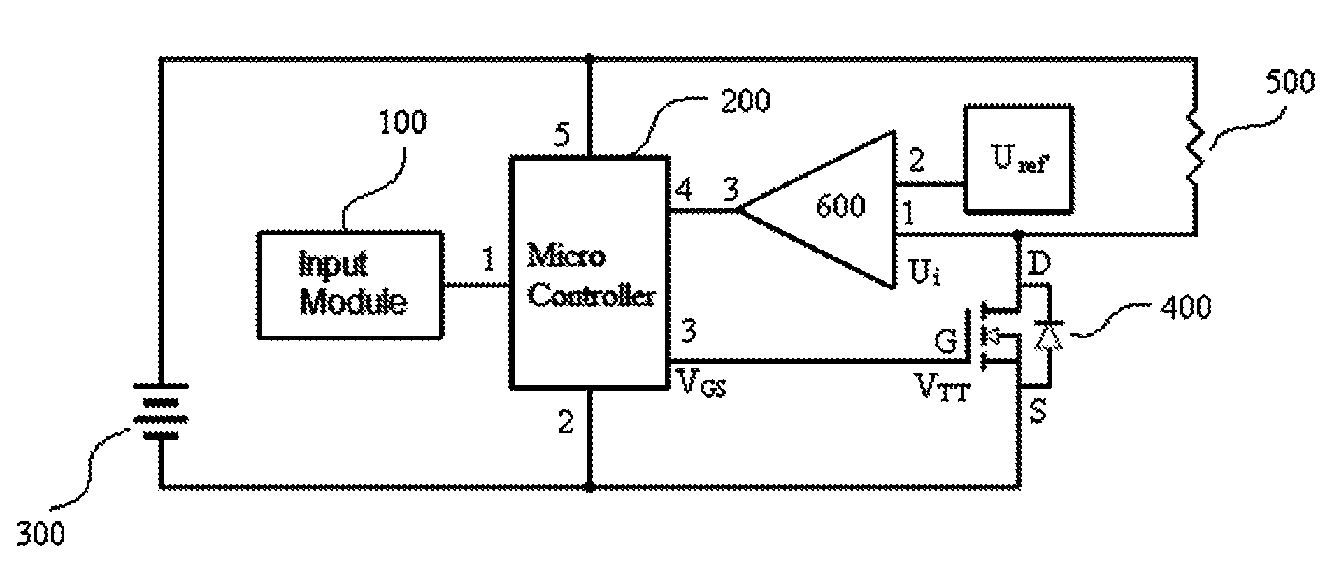
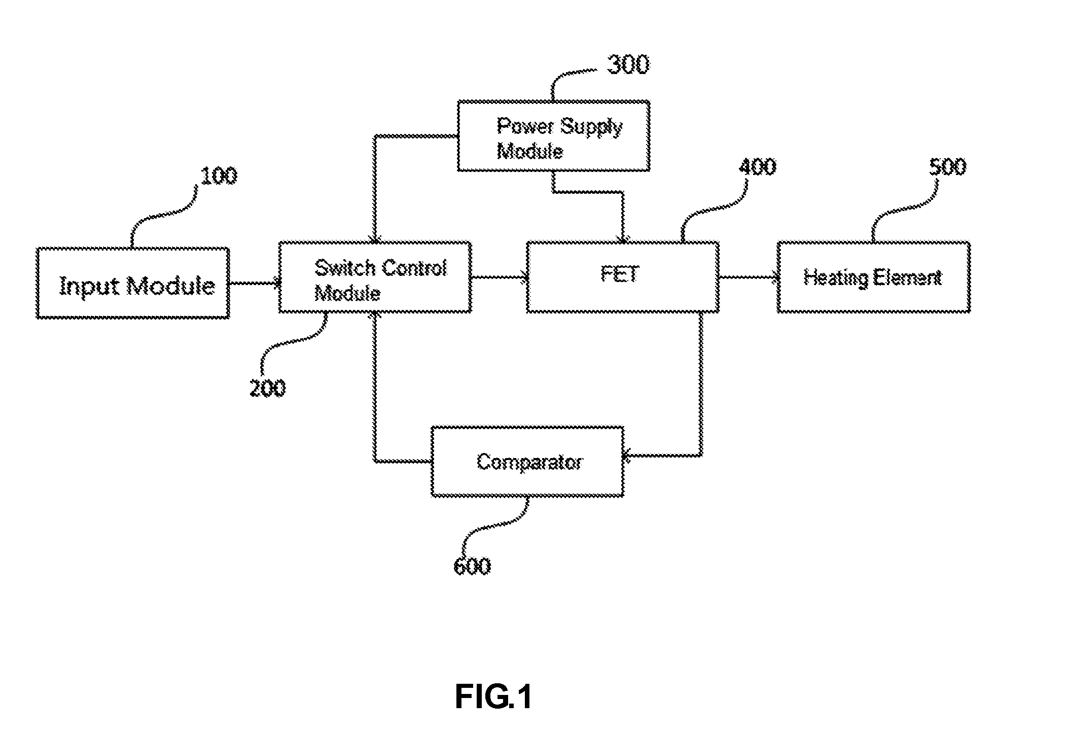
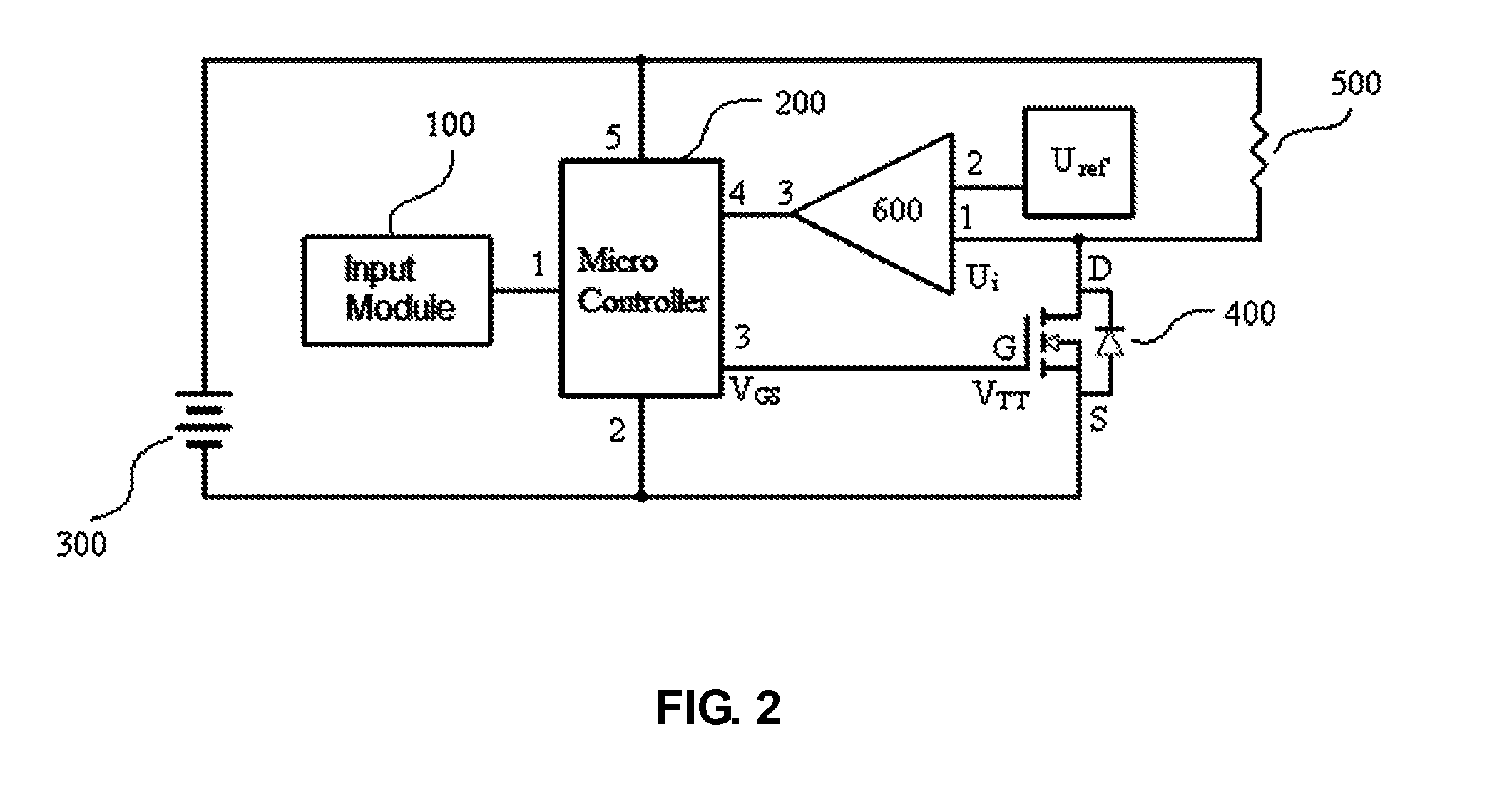
The present invention provides a simple and low-cost control device and method for over current or short circuit protection in electronic cigarettes. The device uses the internal resistance of a field effect transistor (FET) as a current detection sensor, real-time detecting the FET's operating voltage generated by its operating current. This technology eliminates the need for extra current detection sensors such as resistors or current transformers. The controller generates a control signal to the switch control module when over current or short circuit occurs, which turns off the FET and powers off the heating circuit for the electronic cigarette. This technology simplifies the protection circuit, reduces complexity, and lowers costs.

Problems solved by technology

The heating element of the electronic cigarette is prone to the partial short circuit or dead short because of contacting with liquid smoker and moisture, resulting in an over current or short-circuits current in the main circuit of the electronic cigarette.
If the over current or short-circuit current not be cut off soon, it will causes the circuit burning or fire.
Even if some have over current or short-circuit protection circuit, the current detecting sensor inside the protection circuit is configured as a resistor or a current transformer, the protection circuit is relatively complex, and expensive.
The prior art has defects and needs to be improved.

Method used


Image

  • Over Current and Short Circuit Protection Device and Method For Electronic Cigarette
  • Over Current and Short Circuit Protection Device and Method For Electronic Cigarette
  • Over Current and Short Circuit Protection Device and Method For Electronic Cigarette

Examples


Embodiment Construction

[0033]To resolve the problem of the prior art, which was used resistance or current transformer as a current detection sensor, with the relatively complex and expensive protection circuit, the core technology of the present invention is that an internal resistance of the FET is configured as a current detection sensor of an over current or short circuit protection circuit. When an operating current follows through the internal resistance of the FET, an operating voltage of the FET is generated and transmitted to a input terminal of the comparator, the comparator compares the operating voltage with a reference voltage and output a potential signal to switch control module according to the comparison result, if the operating voltage is lower than the reference voltage, the switch control module generates a high potential signal to the FET corresponding the potential signal from the comparator and maintains the FET turning on, then the heating element working continually; If the operat...


PUM


Abstract

The present invention discloses a control device and method for over current or short circuit protection of electronic cigarette. The control device includes an input module, a power module, a heating element, a switch control module, a comparator, and a FET; the FET is used to detect an operating voltage generated by an operating current following through the internal resistance of the FET, and the operating voltage is transmitted to the comparator; the comparator compares a reference voltage with the operating voltage, and output a potential signal to the switch control module, the switch control module turns off the FET or maintains it turning on corresponding to the potential signal, further the FET powers off or powers on the heating element. Therefore the circuit of electronic cigarette is protected in over current or short circuit condition.

Description

CROSS-REFERENCE TO RELATED APPLICATIONS[0001]This non-provisional application claims priority under 35 U.S.C. §119(a) on Patent Application No. 201310069371.0, filed in P.R. China on Mar. 15, 2013, the entire contents of which are hereby incorporated by reference.FIELD OF THE INVENTION[0002]This present invention relates to the field of electric heating products, and in particular, to an over-current and short-circuits protection device and method for electronic cigarette.BACKGROUND OF THE INVENTION[0003]An electronic cigarette, heating and atomizing the liquid smoke in the electronic cigarette, provides a cigarette substitute for smokers. It is becoming more popular. The electronic cigarette comprises a battery, a control circuit, an atomizer having a heating element as well as other units. For some electronic cigarettes, the heating element is activated by the control circuit according to a signal either from an electronic airflow sensor detecting the aspiratory by smokers or from...

Claims


Application Information

Patent Timeline
Patent Type & Authority Applications(United States)
IPC IPC(8): H02H7/20A24F40/10A24F40/51A24F40/53
CPCH02H7/20H02H3/087A24F40/10A24F40/53A24F40/51
Inventor XIANG, ZHIYONG
Owner HUIZHOU KIMREE TECH
Learn More