
Image pickup apparatus, image pickup system, signal processing apparatus, and non-transitory computer-readable storage medium

Active Publication Date: 2014-09-11
CANON KK
View PDF2 Cites 7 Cited by
  • Summary
  • Abstract
  • Description
  • Claims
  • Application Information

AI Technical Summary

Benefits of technology

The present invention is an image pickup system that can accurately detect focus without being affected by the shape of the object or vignetting. The technical effects of this system are improved accuracy and efficiency in image processing.

Problems solved by technology

However, in each of the configurations disclosed in Japanese Patent Laid-open No. 2000-156823, Japanese Patent Laid-open No. 2001-305415, and Japanese Patent Laid-open No. 2010-140013, since the focus detection is performed by using one-dimensional image, it is weak in an object image with a repeated pattern, and an error remains, which is caused by influences of an adding direction of generating an image and an oblique line component included in the object.
Therefore, particularly a focus detection accuracy in the periphery of the screen is deteriorated.

Method used


Image

  • Image pickup apparatus, image pickup system, signal processing apparatus, and non-transitory computer-readable storage medium
  • Image pickup apparatus, image pickup system, signal processing apparatus, and non-transitory computer-readable storage medium
  • Image pickup apparatus, image pickup system, signal processing apparatus, and non-transitory computer-readable storage medium

Examples


embodiment 1

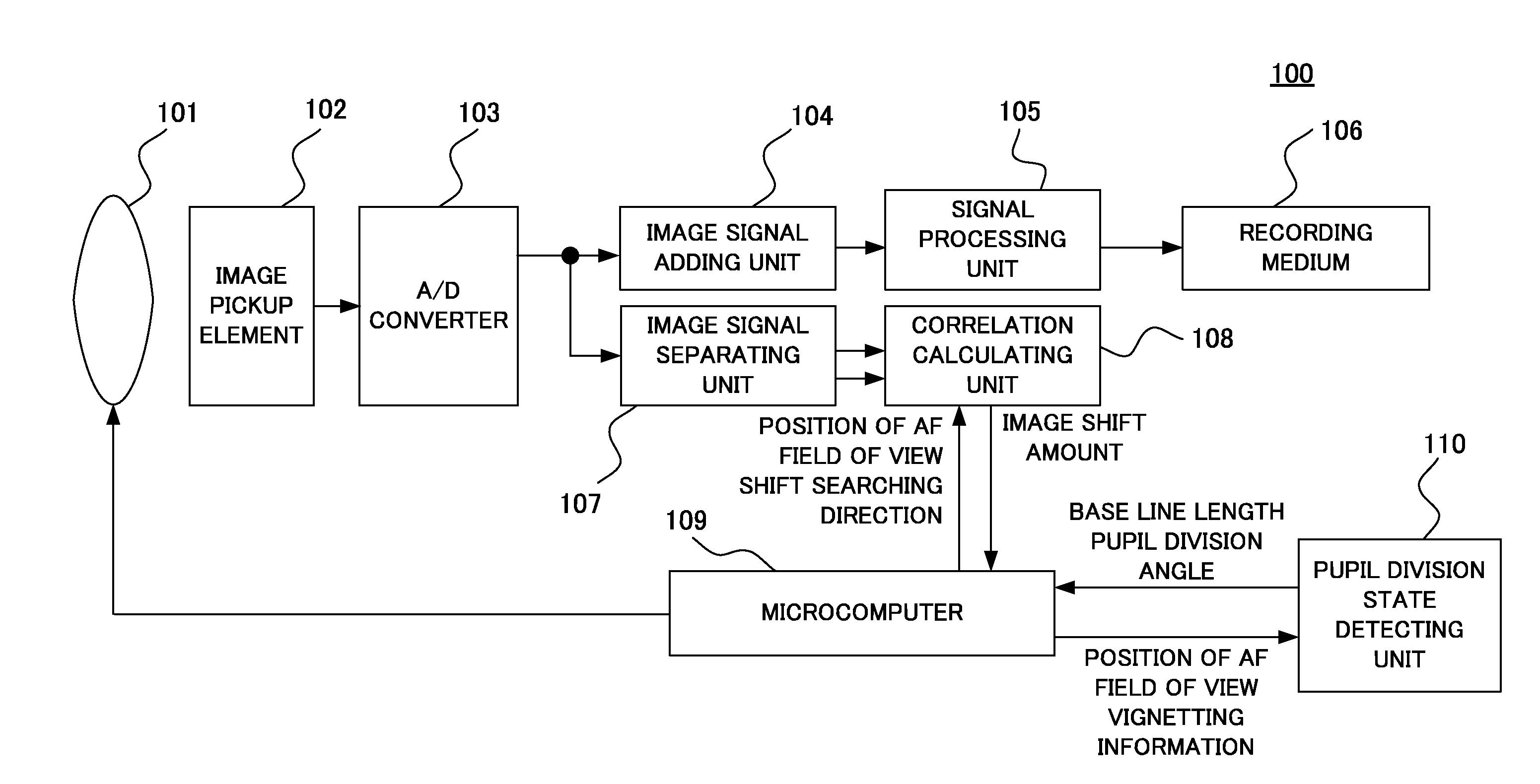
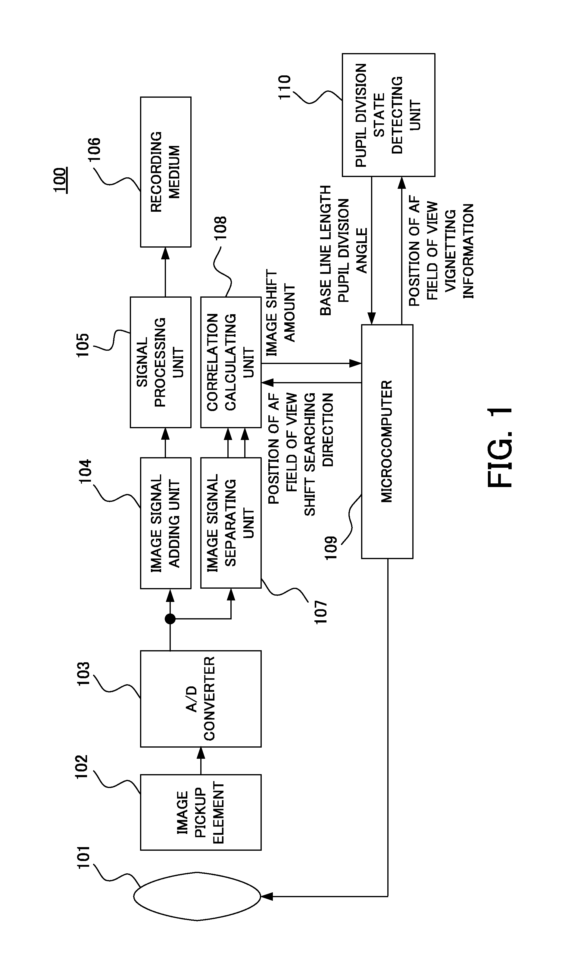
[0041]First of all, referring to FIG. 1, a defocus detection apparatus (an image pickup apparatus) will be described. FIG. 1 is a block diagram of an image pickup apparatus 100 in the present embodiment. In the image pickup apparatus 100, reference numeral 101 denotes a lens unit (an image pickup optical system) including a focus lens or an aperture stop mechanism. In the present embodiment, the image pickup apparatus 100 (an image pickup apparatus body) is configured integrally with the lens unit 101, but the embodiment is not limited to this. The present embodiment can also be applied to an image pickup system that is configured by the image pickup apparatus body and a lens unit removably mounted on the image pickup apparatus body.

[0042]Reference numeral 102 denotes an image pickup element (an image signal generating unit) that has a structure of a pixel illustrated for example in FIG. 2, which photoelectrically converts an object image (an optical image) obtained via an image pic...

embodiment 2

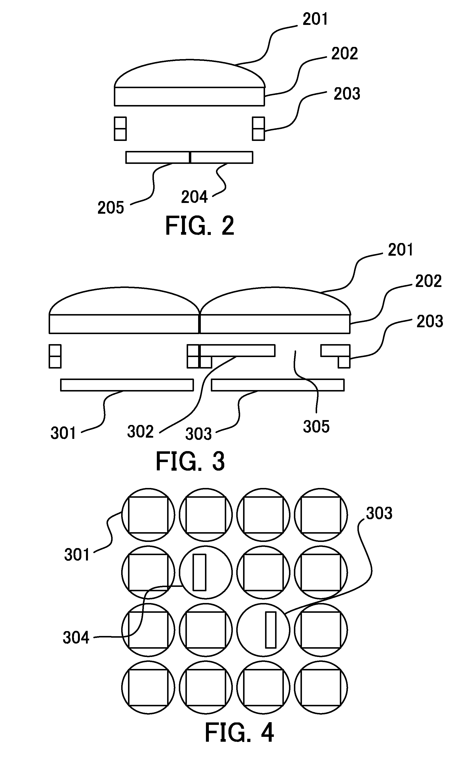
[0061]Next, a defocus detection apparatus (an image pickup apparatus) in Embodiment 2 of the present invention will be described. First of all, referring to FIG. 3, a structure of pixels of an image pickup element in the present embodiment will be described. FIG. 3 is a cross-sectional view of the pixels of the image pickup element in the present embodiment. Reference numeral 201 denotes a microlens, reference numeral 202 denotes a color filter, and reference numeral 203 denotes a wiring layer. Reference numeral 301 denotes a pixel (an image pickup pixel) which is used to generate a normal image signal. Reference numeral 303 denotes a pixel (a focus detection pixel) which is used to generate a focus detection signal. Reference numeral 302 denotes a light blocking portion which extends the wiring layer 203 to an upper portion of the pixel to block the light. With respect to the pixel 303 illustrated in FIG. 3, light enters the pixel 303 only through an opening portion 305 at the righ...


PUM


Abstract

An image pickup apparatus includes an image pickup element including a plurality of focus detection pixels configured to generate a pair of image signals based on light beams passing through pupil regions different from each other in an image pickup optical system, a detection unit configured to detect a base line length of the plurality of focus detection pixels and a pupil division direction based on position information of a focus detection region in the image pickup element and information relating to the image pickup optical system, and a calculation unit configured to calculate a phase difference in the pupil division direction by using the pair of image signals.

Description

BACKGROUND OF THE INVENTION[0001]1. Field of the Invention[0002]The present invention relates to an image pickup apparatus which performs focus detection using light beams passing through pupil regions different from each other in an image pickup optical system.[0003]2. Description of the Related Art[0004]Previously, a focus detection method of using a phase difference detection method has been known. In the phase difference detection method, a light beam passing through an exit pupil of a lens is divided, and the divided light beams are received by a pair of focus detection sensors. Then, a drive amount of the lens required to achieve an in-focus state is obtained based on a shift amount of signals outputted depending on light receiving amounts of the divided light beams, i.e. a relative position shift amount of the light beams in a division direction. Accordingly, since an amount and direction of defocus is obtained when an accumulation is performed once by the focus detection sen...

Claims


Application Information

Patent Timeline
IPC IPC(8): H04N5/232
CPCH04N5/23212H04N23/672H04N25/61H04N25/704G02B7/28G02B7/346
Inventor OGAWA, TAKESHI
Owner CANON KK
Learn More