
Power tool and power tool accessory member

a technology of power tools and accessory parts, which is applied in the field of power tools, can solve the problems and achieve the effect of waste of space occupied by nuts

Inactive Publication Date: 2014-09-11
MAKITA CORP
View PDF26 Cites 21 Cited by
  • Summary
  • Abstract
  • Description
  • Claims
  • Application Information

AI Technical Summary

Benefits of technology

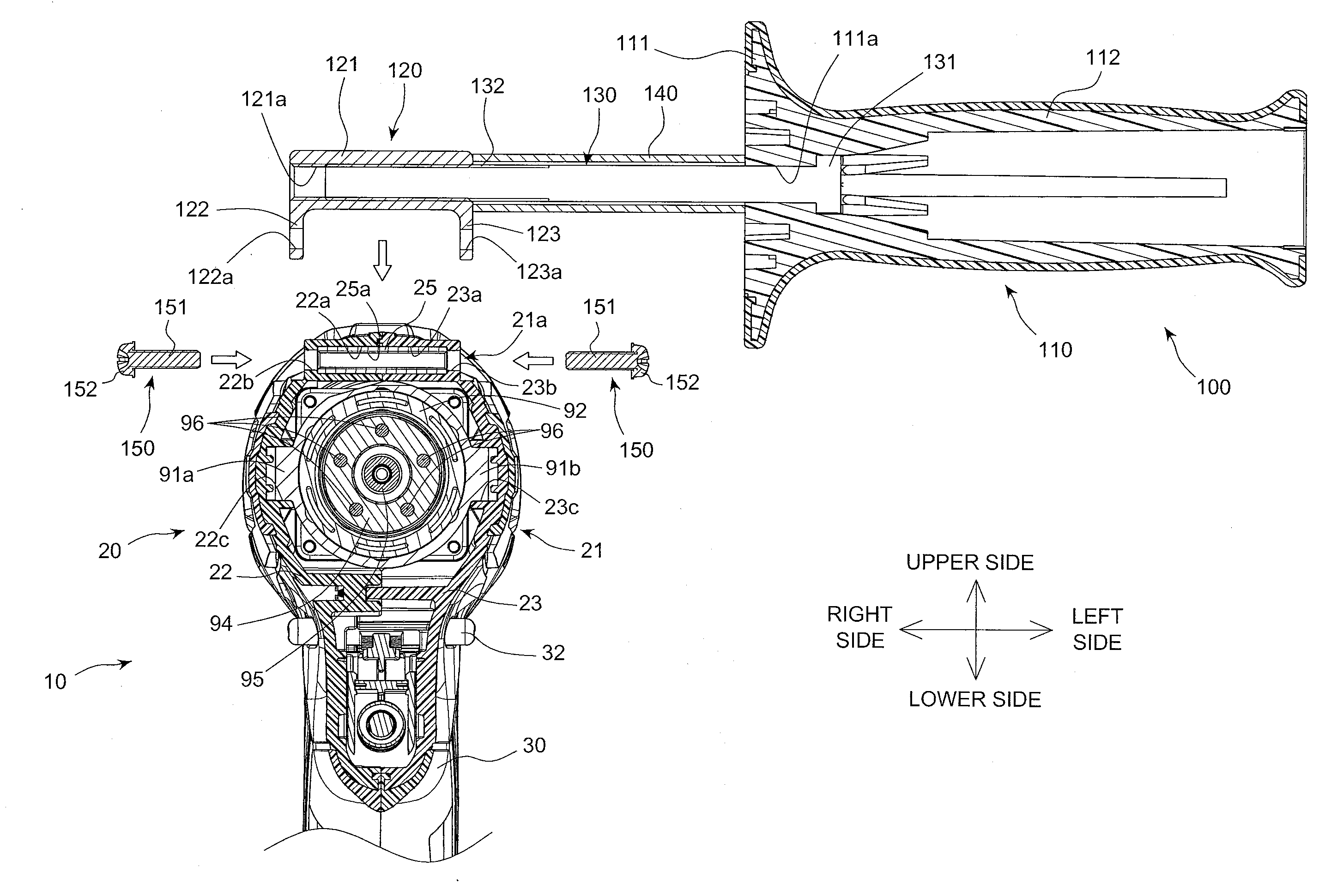
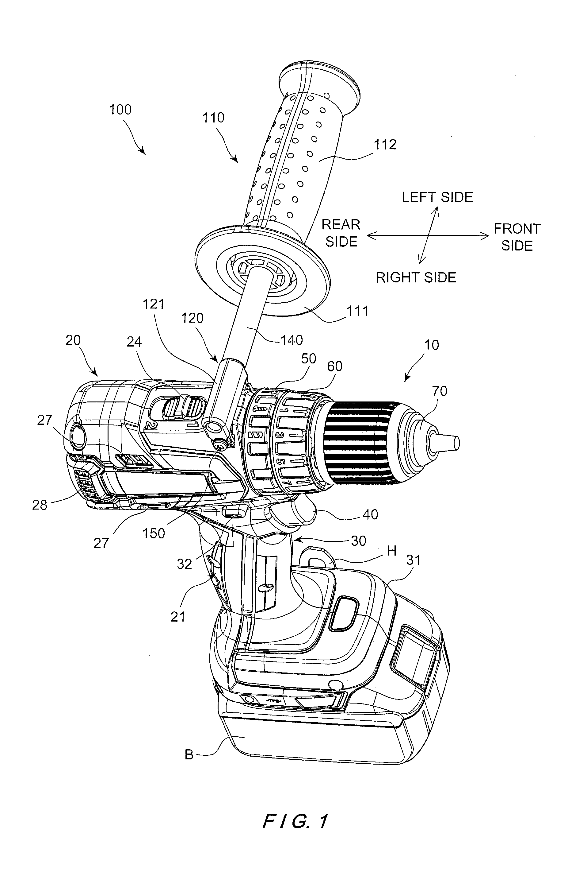
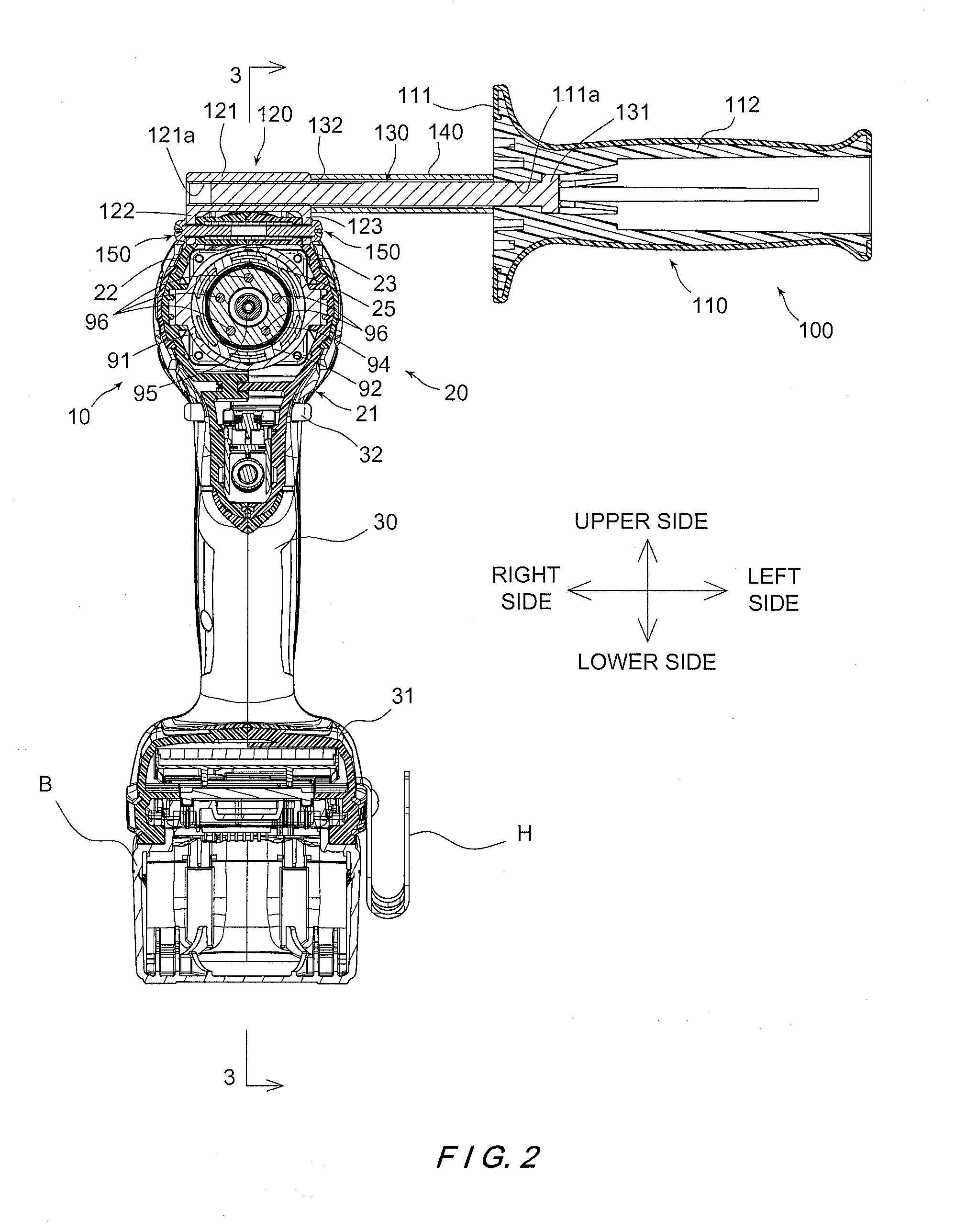
This patent discusses a power tool with a hook attachment structure. In conventional power tools, the nut is only used for attaching the hook member, so when the hook member is not attached, the nut is not use, which wastes space. However, this patent proposes a power tool with a female thread part that can be engaged with a male thread of a power tool accessory member. This allows for more flexibility and utilizing the space occupied by the nut. The technical effect is the improved performance and functionality of the power tool with the power tool accessory member.

Problems solved by technology

Therefore, when the hook member is not attached to the power tool, the nut is also not used, and thus, the space occupied by the nut is wasted.

Method used


Image

  • Power tool and power tool accessory member
  • Power tool and power tool accessory member
  • Power tool and power tool accessory member

Examples


second embodiment

[0044]Referring now to FIGS. 6 to 10, a power tool 10′ with an auxiliary handle member 100′ in accordance with a second embodiment will now be explained. In view of the similarity between the first and second embodiments, the parts of the second embodiment that are identical to the parts of the first embodiment will be given the same reference numerals as the parts of the first embodiment. Moreover, the descriptions of the parts of the second embodiment that are identical to the parts of the first embodiment may be omitted for the sake of brevity. The parts of the second embodiment that differ from the parts of the first embodiment will be indicated with a single prime (′).

[0045]The second embodiment differs from the first embodiment in that a single screw 150′ is used to fixedly couple a bracket member 120′ of the auxiliary handle member 100′ to a main body portion 20′ of the power tool 10′.

[0046]As shown in FIGS. 7, 9 and 10, a nut member 25′ (one example of a female thread part) ...

third embodiment

[0055]Referring now to FIGS. 11 to 15, a power tool 10″ with the auxiliary handle member 100 in accordance with a third embodiment will now be explained. In view of the similarity between the first and third embodiments, the parts of the third embodiment that are identical to the parts of the first embodiment will be given the same reference numerals as the parts of the first embodiment. Moreover, the descriptions of the parts of the third embodiment that are identical to the parts of the first embodiment may be omitted for the sake of brevity. The parts of the third embodiment that differ from the parts of the first embodiment will be indicated with a double prime (″).

[0056]The power tool 10″ of the third embodiment differs from the power tool 10 of the first embodiment in that a nut member 25″ is supported by a front gear case 91″ of a gear assembly 90″ in the third embodiment. The structure of the auxiliary handle member 100 of the third embodiment is identical to the structure o...


PUM

PropertyMeasurementUnit
shapeaaaaaaaaaa
rotational speedaaaaaaaaaa
areaaaaaaaaaaa

Abstract

A power tool includes a motor unit, a main body portion, a grip portion and a female thread part. The main body portion accommodates the motor unit therein. The grip portion extends from the main body portion. The female thread part is retained to the main body portion. The female thread part includes a female thread configured and arranged to engage with a male thread of a male thread part of a power tool accessory member.

Description

BACKGROUND[0001]1. Field of the Invention[0002]The present invention generally relates to a power tool. More specifically, the present invention relates to a power tool with a power tool accessory member removably coupled to the power tool.[0003]2. Background Information[0004]Conventional power tools are often used with accessory members such as a hook member, a lighting unit, an auxiliary handle member, and the like. For example, Japanese Utility Model Patent Application Publication No. H5-4168 discloses a hook attachment structure for a power tool. In this publication, the hook member formed by bending a plate shaped element is fixed to the power tool by a bolt that threadedly engages a nut disposed within a housing or a handle cover in a grip portion.SUMMARY[0005]In the conventional hook attachment structure for the power tool as discussed above, the nut is provided only for the purpose of attaching the hook member. Therefore, when the hook member is not attached to the power too...

Claims


Application Information

Patent Timeline
Patent Type & Authority Applications(United States)
IPC IPC(8): B25F5/02
CPCB25F5/02B25F5/026
Inventor KONDO, TOMOYUKI
Owner MAKITA CORP
Learn More