
Communication system and communication device

Active Publication Date: 2014-09-04
SUMITOMO ELECTRIC IND LTD +3
View PDF9 Cites 5 Cited by
  • Summary
  • Abstract
  • Description
  • Claims
  • Application Information

AI Technical Summary

Benefits of technology

The present invention allows for reliable communication by adding a communication signal to a control pilot line. This improves the effectiveness and efficiency of communication.

Problems solved by technology

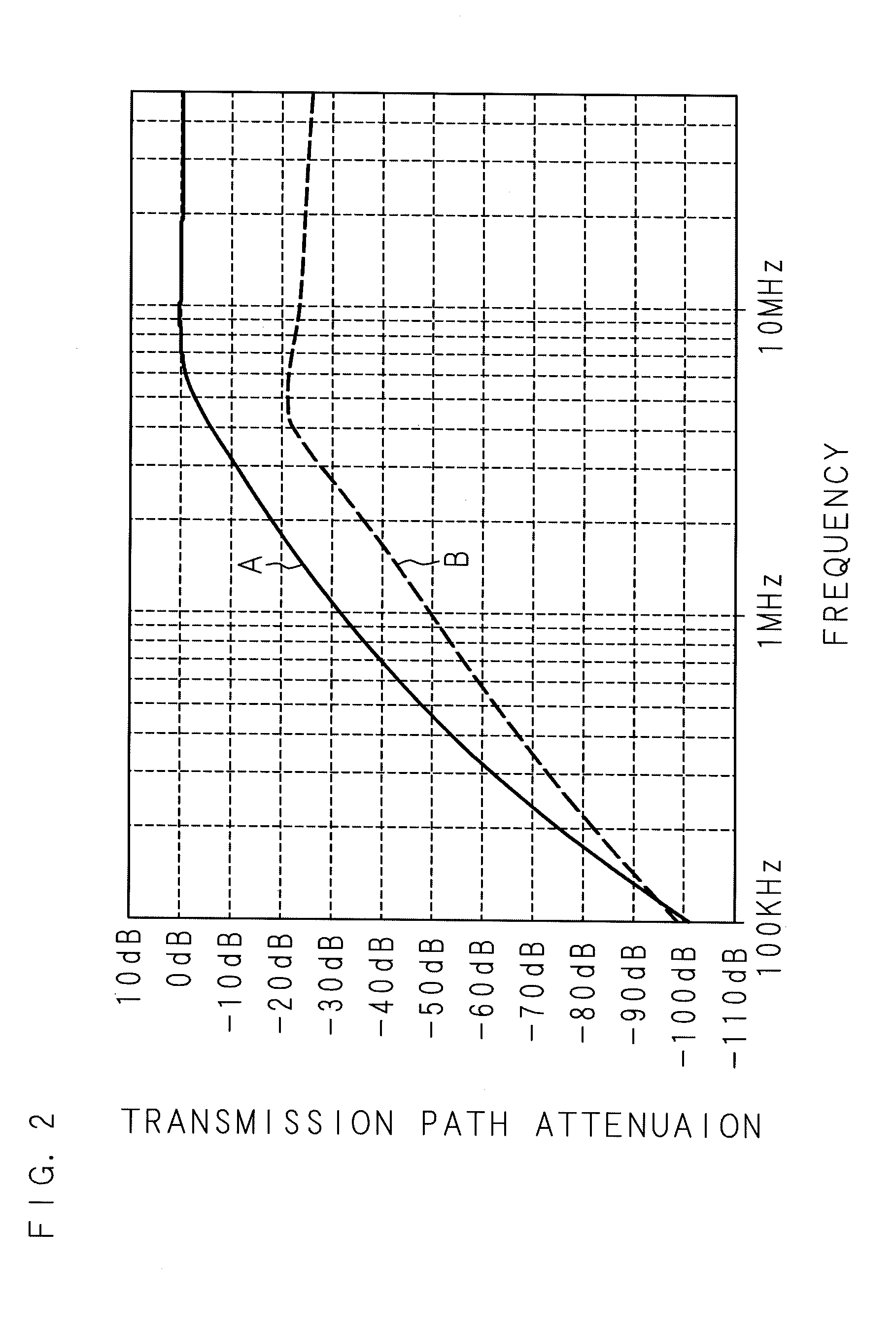
This causes a possibility of degradation in the transmission speed or degradation in the noise resistance.
Further, when the communication circuit superimposing the communication signal is connected to the control pilot line, a possibility also arises that transmission and reception of the control pilot signal is not achieved owing to the influence of the communication circuit.

Method used


Image

  • Communication system and communication device
  • Communication system and communication device
  • Communication system and communication device

Examples


embodiment 1

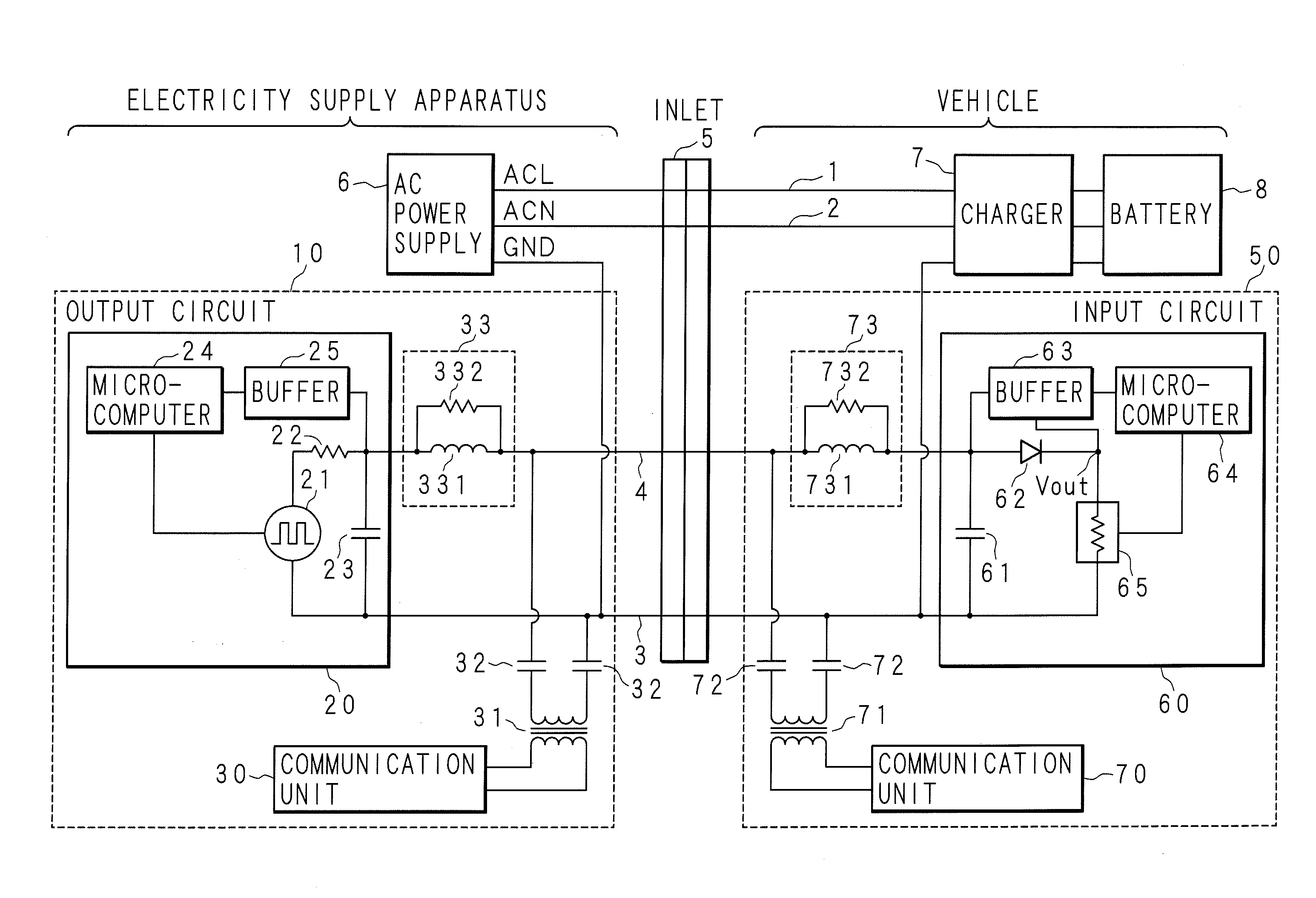
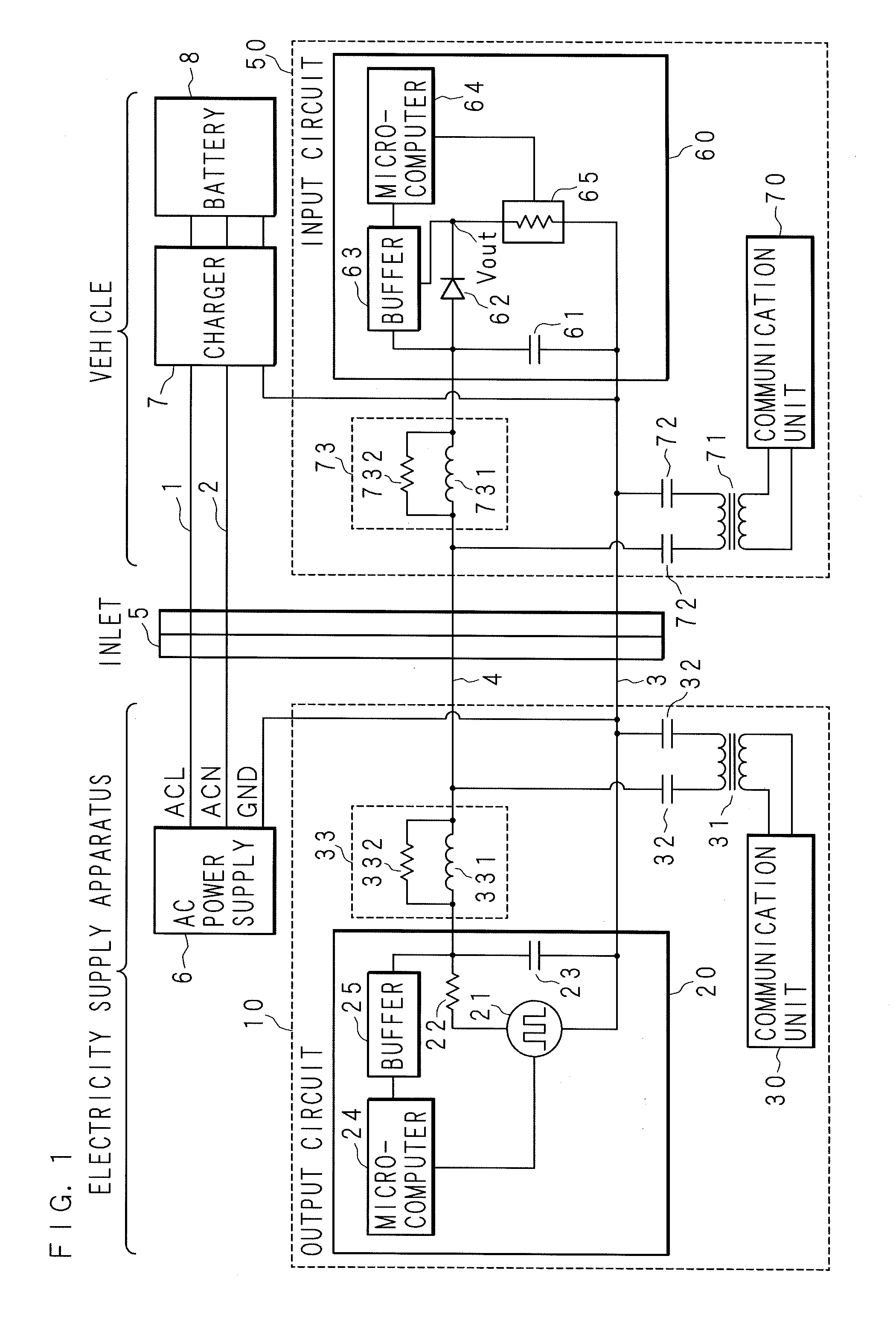
[0041]An embodiment of a communication system according to the present invention is described below with reference to the drawings. FIG. 1 is a block diagram illustrating an example of the configuration of the communication system according to Embodiment 1. As illustrated in FIG. 1, a vehicle such as an electric car and a hybrid car is electrically connected to an electricity supply apparatus via an inlet 5 (also referred to as a “power feed opening” or a “connector”). The electricity supply apparatus includes an AC power supply 6. The AC power supply 6 is electrically connected to a charger 7 of the vehicle via a power supply line 1 (ACL) and a power supply line 2 (ACN). The charger 7 is connected to a battery (a secondary battery) 8.

[0042]Thus, when a plug (not illustrated) connected to a charging cable from the electricity supply apparatus is connected to the inlet 5, AC electricity is supplied to the vehicle and hence the battery 8 mounted on the vehicle is charged.

[0043]The com...

embodiment 2

[0098]FIG. 10 is a block diagram illustrating an example of the configuration of a communication system according to Embodiment 2. The difference from Embodiment 1 is that the lowpass filter 33 includes an inductor 331 and a series circuit constructed from a capacitor 333 and a resistor 334 connected between the control pilot line 4 and the ground line 3. Similarly, the lowpass filter 73 includes an inductor 731 and a series circuit constructed from a capacitor 733 and a resistor 734 connected between the control pilot line 4 and the ground line 3. Here, like parts to Embodiment 1 are designated by like numerals and their description is omitted.

[0099]By virtue of this configuration, the Q factor (Quality factor) representing the sharpness of the peak of resonance in the resonance circuit formed between the inductor and the capacitor provided in the output circuit or the input circuit is reduced so that unnecessary resonance is suppressed.

[0100]The present embodiment may be applied t...


PUM


Abstract

Provided are a communication system and a communication device capable of suppressing attenuation of a communication signal superimposed upon a control pilot line. This output circuit (20) sends a control pilot signal which has been generated at a voltage generation source (21) to an input circuit (60). Between the control pilot line (4) and the ground line (3) of the output side of the output circuit (20), a communication unit (30) is connected via a transformer (31). Between the control pilot line (4) and the ground line (3) of the input side of the input circuit (60), a communication unit (70) is connected via a transformer (71). Between the output circuit (20) and the transformer (31), a lowpass filter (33) is interposed. Between the input circuit (60) and the transformer (71), a lowpass filter (73) is interposed.

Description

CROSS-REFERENCE TO RELATED APPLICATIONS[0001]This application is the national phase under 35 U.S.C. §371 of PCT International Application No. PCT / JP2012 / 065847 which has an International filing date of Jun. 21, 2012 and designated the United States of America.BACKGROUND[0002]1. Technical Field[0003]The present invention relates to: a communication system achieving communication between a vehicle such as an electric car and hybrid car and an electricity supply apparatus supplying electricity to the vehicle; and a communication device constituting this communication system.[0004]2. Description of Related Art[0005]In recent years, as techniques used for treating global warming, attention is focused on environmental technology. As such environmental technology, for example, electric cars, hybrid cars, and the like in which a secondary battery is mounted and an electric motor is employed as a drive unit in place of a conventional combustion engine that consumes gasoline have been brought...

Claims


Application Information

Patent Timeline
IPC IPC(8): H04B3/54
CPCH04B3/54Y02T90/16Y02T90/14Y04S10/126Y04S30/14H04B3/548H04B2203/547B60L2210/30Y02T10/7072B60L53/14B60L53/64B60L53/63B60L53/65H02J7/00036H02J7/00047Y02E60/00Y02T10/72Y02T10/70Y02T90/12Y02T90/167
Inventor KOMATSU, YUTAKAHAGIHARA, TAKESHIOKADA, RYOUTAKATA, YOUSUKEIZUMI, TATSUYANII, KAZUHIKOANDOH, HIROYAOCHIAI, YUTAKAMAGA, RYUICHIIWAI, ATSUSHIMIYASHITA, YUKIHIRONAKAGAWA, NOBUYUKI
Owner SUMITOMO ELECTRIC IND LTD
Learn More