
High-efficiency LED illuminator with improved beam quality

a technology of led illuminators and beams, applied in the field of led illuminators, can solve the problems of poor light generation by existing light-emitting diodes (led) illuminators, poor light uniformity, and inability to achieve color separation at the edge of beams, etc., and achieve the effect of increasing the light collection efficiency of leds

Active Publication Date: 2014-09-04
GEN SCI
View PDF3 Cites 10 Cited by
  • Summary
  • Abstract
  • Description
  • Claims
  • Application Information

AI Technical Summary

Benefits of technology

The patent allows for adjustable distance between the lenses and the LED to achieve better light collection. Additionally, a conical mirror can be used to improve light efficiency. The technical effect is improved performance and efficiency of LED lighting systems.

Problems solved by technology

The light generated by existing light-emitting diode (LED) illuminators is quite poor.
As such, this and other existing configurations exhibit poor light uniformity and / or unacceptable color separation at the edge of beam.

Method used


Image

  • High-efficiency LED illuminator with improved beam quality
  • High-efficiency LED illuminator with improved beam quality
  • High-efficiency LED illuminator with improved beam quality

Examples


Embodiment Construction

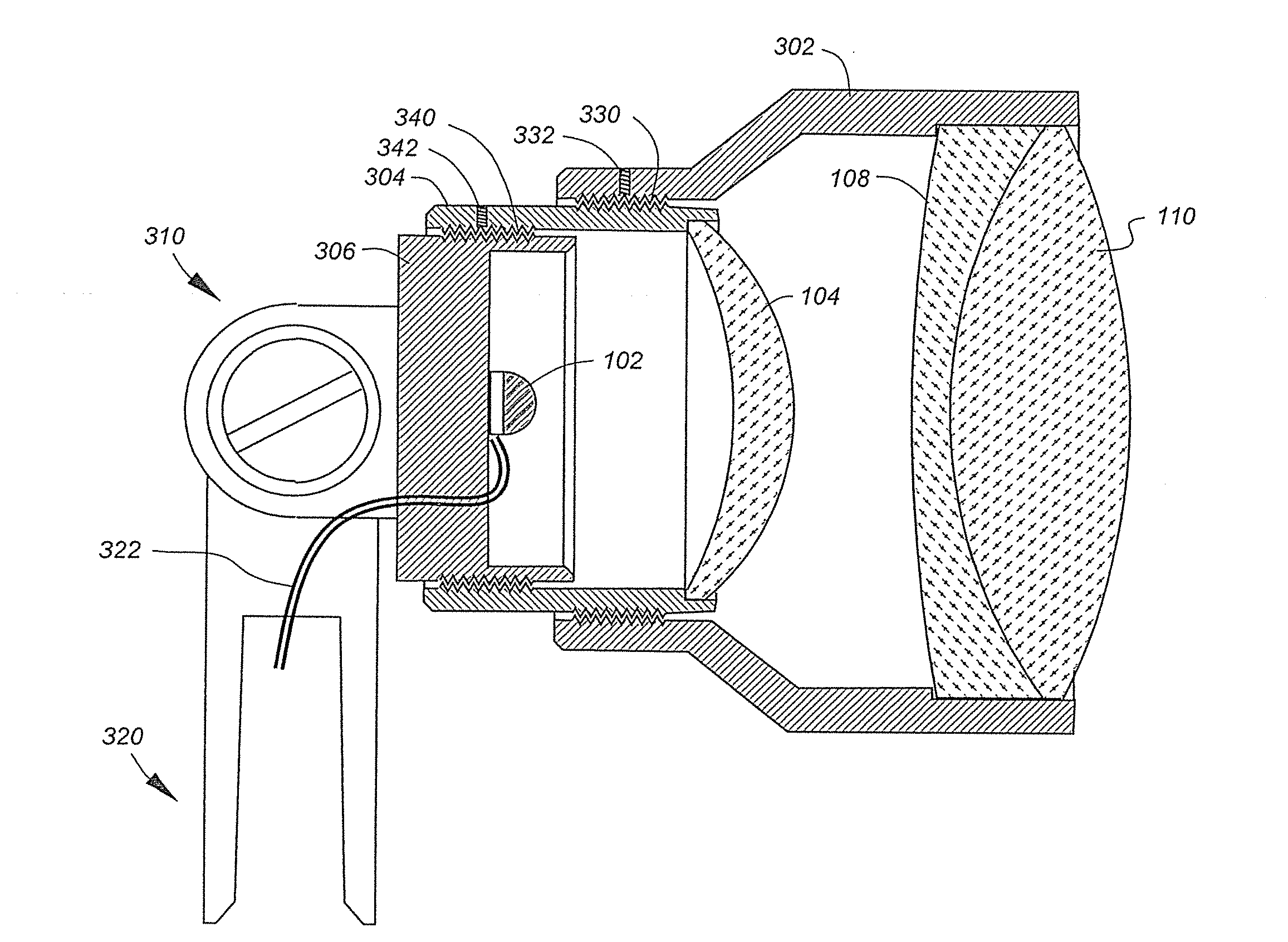
[0013]This invention resides in an LED illuminator with multiple optical elements to improve beam quality. All embodiments include a housing with an LED source, a singlet lens supported in front of the LED, and an achromatic doublet lens in position where the light exits the housing. An attachment mechanism is coupled to the housing, enabling the illuminator to be worn as a headlamp.

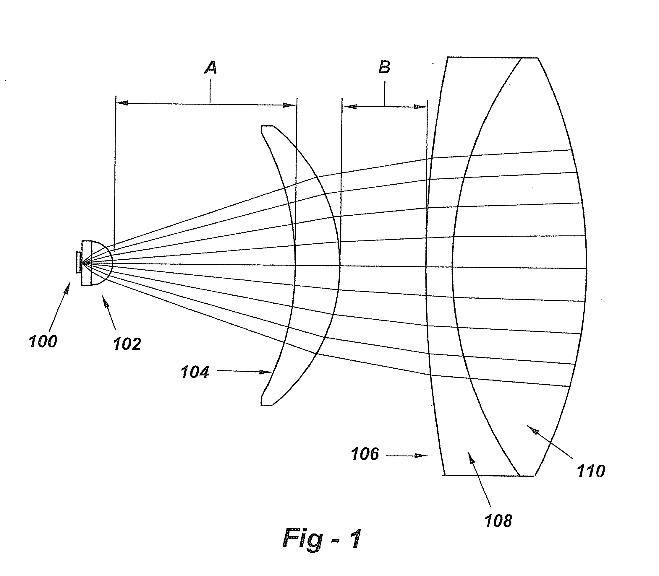
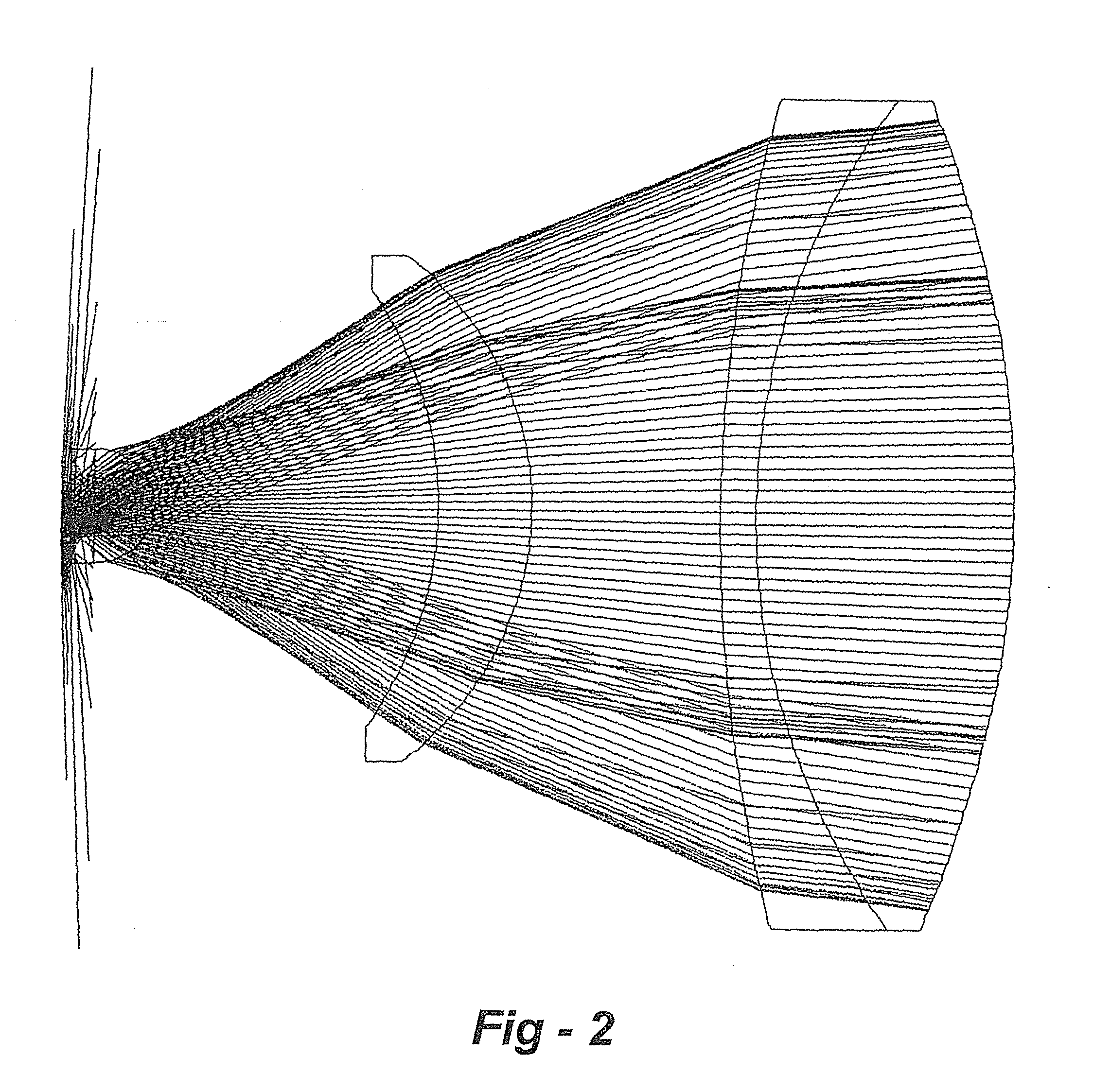
[0014]One embodiment, shown in FIG. 1, uses a singlet lens 104 and an achromatic doublet lens 106 made with one positive and one negative lens elements 108, 110. This and the other embodiments disclosed herein are based upon a high-intensity white-emitting LED 100 including an integral lens 102, which may be spherical.

[0015]One or both distances A, B in FIG. 1 can be either fixed or adjustable for beam pattern or different applications. For typical headlamp applications, A may be on the order of 6 mm, adjustable between 4 to 11 mm, while B may be on the order of 4 mm, adjustable between 2 to 6 mm or ther...


PUM


Abstract

An improved illuminator with an adjustable beam pattern to be worn by medical and dental professionals includes a housing, a light-emitting diode (LED) disposed in the housing outputting light through a distal opening in the housing, an achromatic doublet lens mounted in the opening in the housing, and a singlet lens disposed between the LED and the achromatic lens. The distance between the singlet lens and the doublet lens may be adjustable, and / or distance between the LED and the singlet lens may be adjustable, through a threaded connections, for example. In the preferred embodiment, the achromatic doublet lens, the singlet lens, or both the singlet and the doublet lens have a planar surface. A conical mirror may be disposed between the LED and the singlet lens to increase the light collection efficiency of the LED.

Description

REFERENCE TO RELATED APPLICATIONS[0001]This patent application is a continuation-in-part of U.S. patent application Ser. No. 13 / 216,866, filed Aug. 24, 2011, which is a continuation-in-part of U.S. patent application Ser. No. 12 / 623,470, filed Nov. 23, 2009, the entire content of both of which is incorporated herein by reference.FIELD OF THE INVENTION[0002]This invention relates generally to illuminators of the type worn by medical and dental professionals and, in particular, to an LED illuminator with multiple optical elements to improve beam qualityBACKGROUND OF THE INVENTION[0003]The light generated by existing light-emitting diode (LED) illuminators is quite poor. Current illuminators of this kind use reflecting optical elements or singlet or multiple lenses with reflecting optical elements. An example is shown in U.S. Pat. No. 3,745,993 entitled “Surgical Headlight.” Although this design discloses an achromatic lens, the light delivered to it from an optical fiber is reflected ...

Claims


Application Information

Patent Timeline
Patent Type & Authority Applications(United States)
IPC IPC(8): F21V13/04F21V21/084F21K99/00F21V5/00
CPCF21K9/58F21V13/04F21V5/008F21V21/084F21V14/02F21Y2101/02F21V14/065F21V21/0885F21W2131/205F21V14/025F21V5/048F21V14/06F21V21/30F21W2131/202F21Y2115/10
Inventor CHANG, BYUNG, J.
Owner GEN SCI
Learn More