Solar light-control module

a technology of solar cells and light control, applied in the direction of photovoltaics, electrical apparatus, semiconductor devices, etc., can solve the problems of low light-collection efficiency, bulky commercial solar cells, inconvenient use, etc., and achieve the effect of improving light-collection efficiency and low fabrication cos

Active Publication Date: 2014-09-09
WINTEK CHINA TECH LTD +1
View PDF22 Cites 0 Cited by
  • Summary
  • Abstract
  • Description
  • Claims
  • Application Information

AI Technical Summary

Benefits of technology

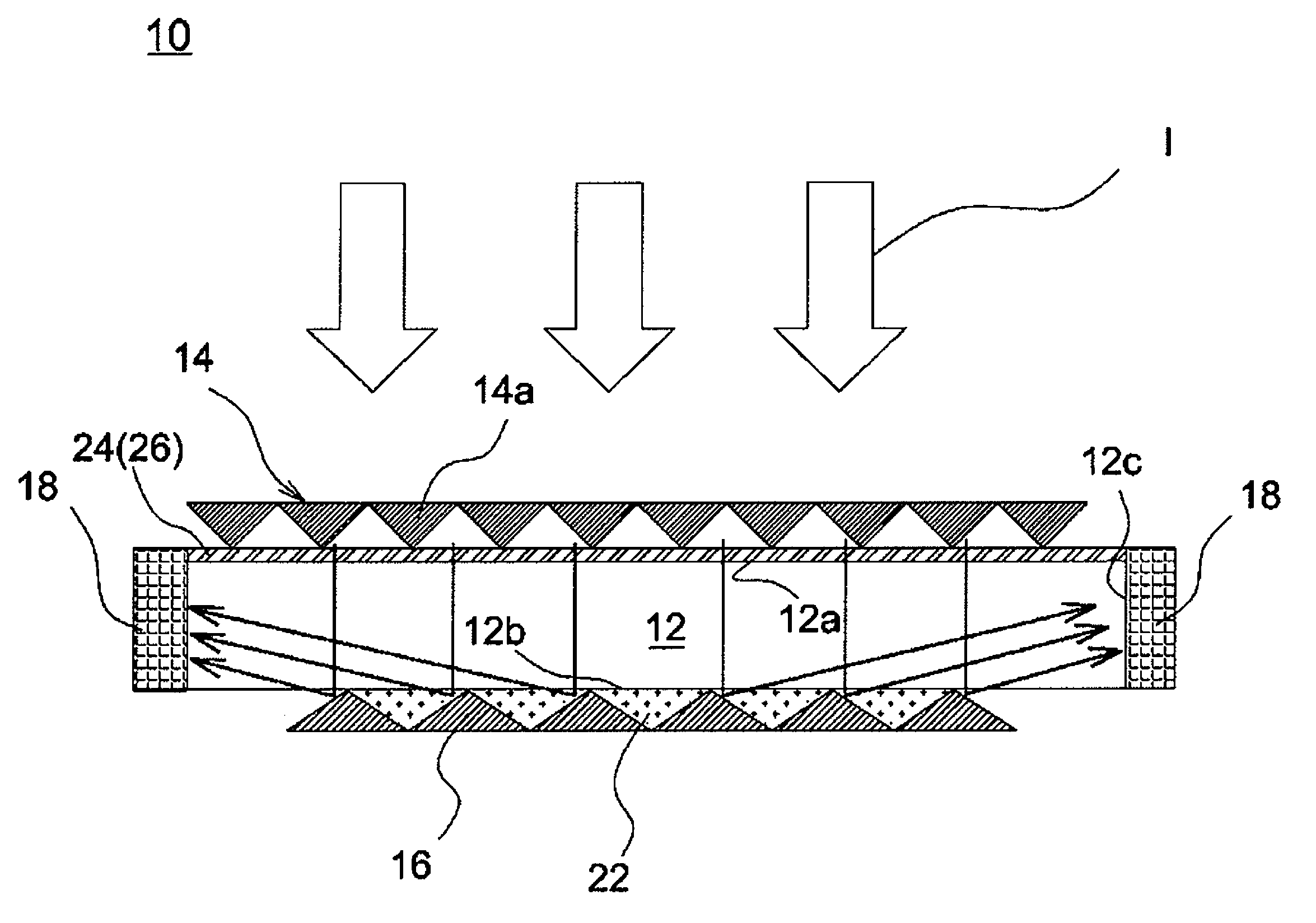
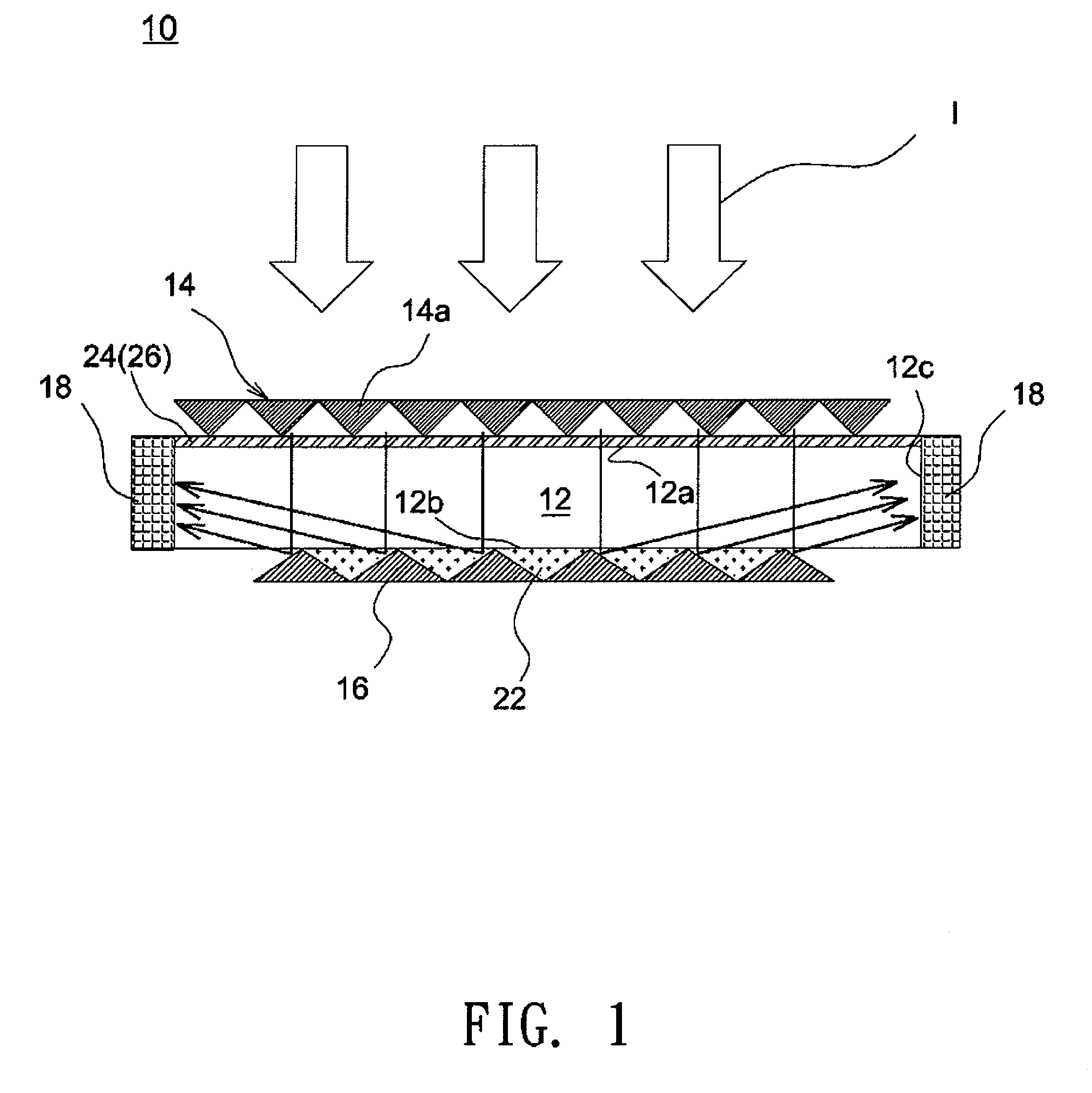
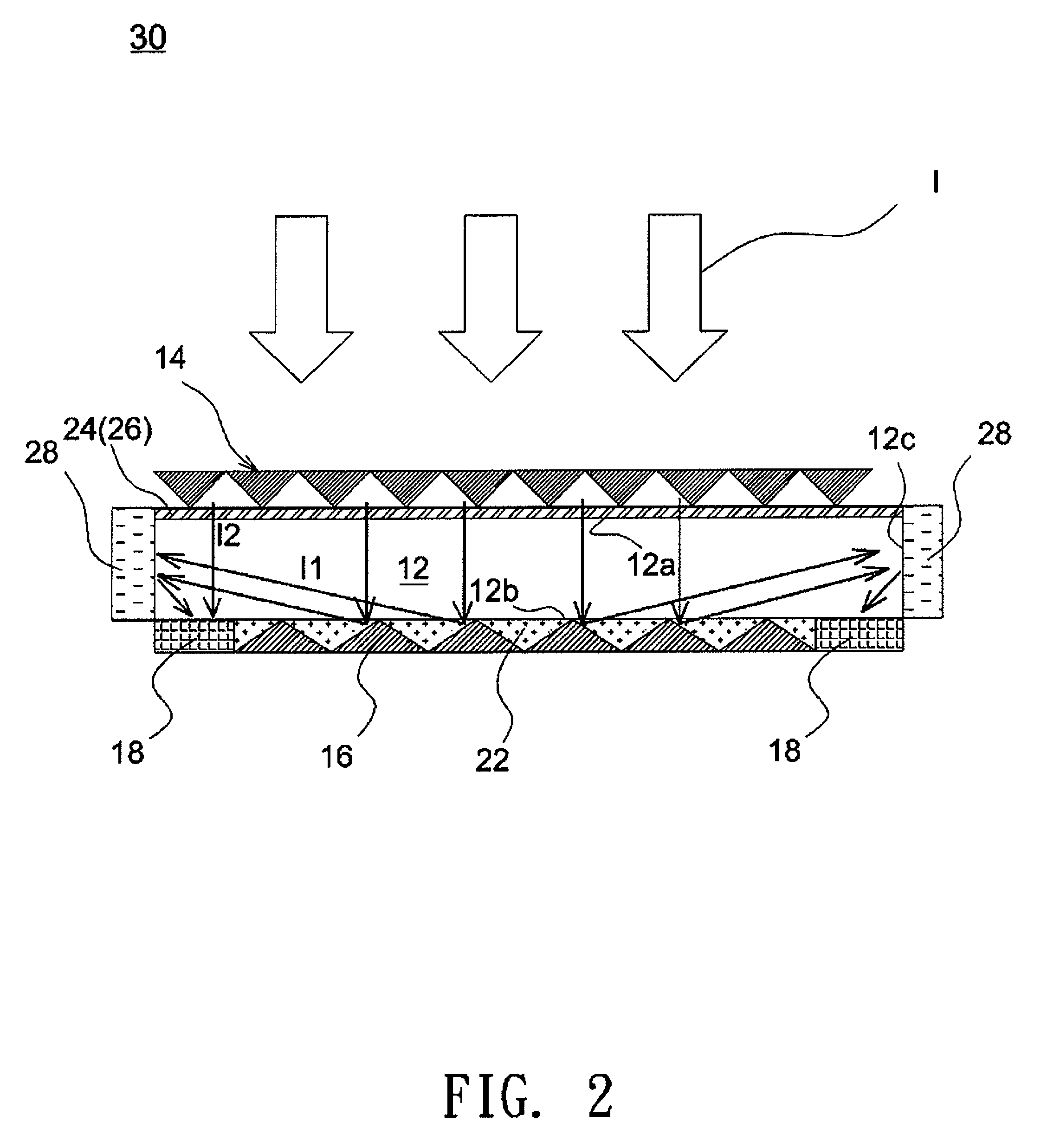
[0005]The invention provides a solar light-control module having improved light-collection efficiency and low fabrication costs.
[0013]According to the above embodiments, since the ambient light are deflected by the micro strictures to propagate sideways in the light-propagation chamber, the ambient light are allowed to be concentrated with high intensity on a comparatively small predetermined area instead of spreading over a wide area, and thus the solar cell is allowed to be disposed on the comparatively small predetermined area to effectively reduce the occupied area of the solar cell and enhance the light-collection efficiency.

Problems solved by technology

Nowadays, a commercial solar cell is bulky and has low light-collection efficiency (low optical energy received per unit area).
Though a Fresnel lens may be installed in a solar cell to condense light and improve the light-collection efficiency as a result, the Fresnel lens must rotate according to the solar azimuth to result in an inconvenient use.
Besides, the installation of the Fresnel lens considerably increases the fabrication cost and occupied space of a solar cell module.

Method used


Image

  • Solar light-control module
  • Solar light-control module
  • Solar light-control module

Examples


Embodiment Construction

[0021]In the following detailed description of the preferred embodiments, reference is made to the accompanying drawings which form a part hereof, and in which are shown by way of illustration specific embodiments in which the invention may be practiced. In this regard, directional terminology, such as “top,”“bottom,”“front,”“back,” etc., is used with reference to the orientation of the Figure(s) being described. The components of the present invention can be positioned in a number of different orientations. As such, the directional terminology is used for purposes of illustration and is in no way limiting. On the other hand, the drawings are only schematic and the sizes of components may be exaggerated for clarity. It is to be understood that other embodiments may be utilized and structural changes may be made without departing from the scope of the present invention. Also, it is to be understood that the phraseology and terminology used herein are for the purpose of description an...


PUM


Abstract

A solar light-control module includes a light-propagation chamber, a plurality of micro structures, a refractive media, and at least one solar cell. The light-propagation chamber has a first face, a second face and at least one side surface. Ambient light is incident to the first face to enter the solar light-control module. The micro structures are disposed on the second face to deflect the ambient light and guide the ambient light to a predetermined area of the light-propagation chamber. The refractive media is disposed between the second face of the light-propagation chamber and the micro structures, and the solar cell is disposed on the predetermined area.

Description

BACKGROUND OF THE INVENTION[0001]a. Field of the Invention[0002]The invention relates to a solar light-control module.[0003]b. Description of the Related Art[0004]Nowadays, a commercial solar cell is bulky and has low light-collection efficiency (low optical energy received per unit area). Though a Fresnel lens may be installed in a solar cell to condense light and improve the light-collection efficiency as a result, the Fresnel lens must rotate according to the solar azimuth to result in an inconvenient use. Besides, the installation of the Fresnel lens considerably increases the fabrication cost and occupied space of a solar cell module.BRIEF SUMMARY OF THE INVENTION[0005]The invention provides a solar light-control module having improved light-collection efficiency and low fabrication costs.[0006]According to an embodiment of the invention, a solar light-control module includes a light-propagation chamber, a plurality of micro structures, a refractive media, and at least one sola...

Claims


Application Information

Patent Timeline
Patent Type & Authority Patents(United States)
IPC IPC(8): H01L31/052
CPCH01L31/0525H01L31/0524Y02E10/52H01L31/0547H01L31/0543
Inventor WANG, WEN-CHUNYE, ZHI-TINGLIU, CHUN-CHIA
Owner WINTEK CHINA TECH LTD
Why Eureka
Try Eureka