
Hydromotive Machine

a technology of hydropower and motors, applied in the direction of machines/engines, electric generator control, liquid fuel engines, etc., can solve the problems of reducing power generation, reducing the resistance of flow, and shutting down one or more operable machines, so as to achieve the effect of minimal resistance to flow

Inactive Publication Date: 2014-09-04
OBERMEYER HENRY
View PDF6 Cites 9 Cited by
  • Summary
  • Abstract
  • Description
  • Claims
  • Application Information

AI Technical Summary

Benefits of technology

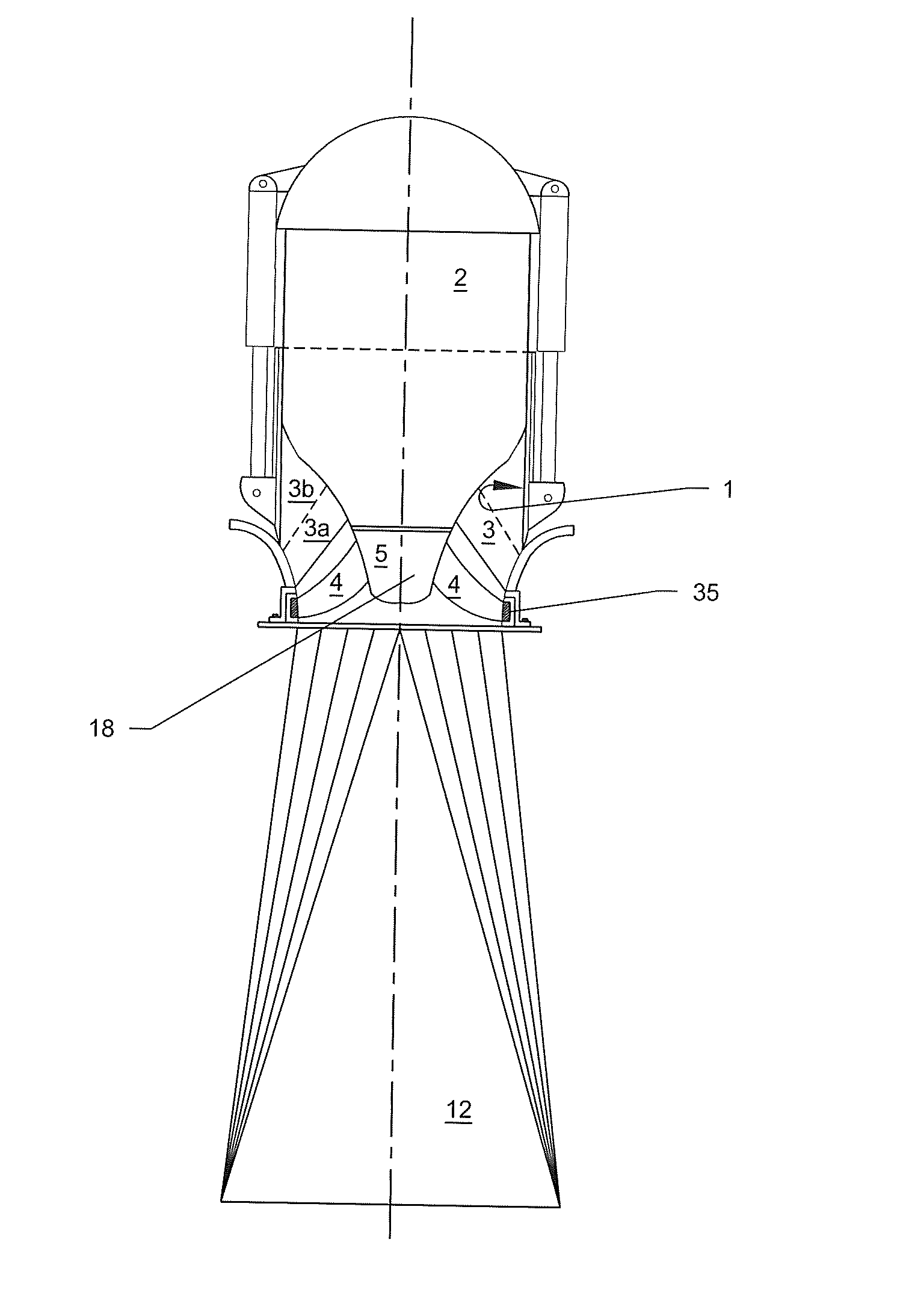
This patent provides a compact and integrated shut-off means for hydromotive machines such as pumps, turbines, or pump-turbines with submersible motors, generators or motor-generators. The invention includes a cylinder gate that can be opened and closed to control the flow of fluid through the machine. A small gap is provided between the cylinder gate and the generator housing to allow for water cooling of the generator. Bearing elements are attached to both the cylinder gate and the generator housing to guide the cylinder gate between its open and closed positions and to wipe any accumulated scum off the surfaces of the generators. The bearing elements also allow water flow between the generator housing and the stator outside diameter. This invention simplifies the process of shutting off hydromotive machines and ensures safe and reliable operation.

Problems solved by technology

Such valves require relatively large actuators while the valve causes backpressure on the draft tube and a reduction in power generation.
This results in having to shut down one or more operable machines even if only one of the machines associated with a multi-aperture ring follower valve must be shut down due to a mechanical or electrical fault condition.
It is not possible with vertical ring follower gates to start the lowest rows first at low flows, followed by starting up upper rows after the tailwater is higher (as a result of higher flows).
Within the high power density assemblies required to economically develop the power potential at existing gated structures there is generally not space enough available for installation of the independently operated ring follower valves that would be required for turning on and off individual machines.
Ring Follower valves also cause undesirable vibration of the rotating assembly during start up and shut down and are ill-suited to sluicing water (discharging water at partial openings with the generator off, as is required at many facilities after a load rejection).
Even though ring follower valves are much smaller than a draft tube gate located at the end of a draft tube, significant force is required for closure.
Slide gates at the ends of draft tubes are heavy, expensive and require large actuators and hydraulic supplies.
Additionally, the guide slots result in head losses at the draft tube exits due to losses across the slots themselves as well as losses due to the narrowing of the draft tubes that is required to accommodate the slide gate slots.
Multi-aperture gate leaves minimize assembly size but reduce flexibility of operation because all of the machines controlled by a single multi-aperture ring follower gate must be turned on and off together as a group.
Pre-existing downstream gates may be used to control arrays of hydromotive machines, however, their use, as in the case of multi-aperture ring follower valves results in reduced flexibility of operation and reduced power generation for run-of-river operations.
No attempt was made to recover the profile loss of the generator housing which ended abruptly at the end of the draft tube.
In general such installations have rather poor efficiency when the flow goes through the runner first then over the generator.
A split discharge ring is expensive.
Provision of a block-out in the powerhouse structure that surrounds the split spherical discharge ring is also expensive.
A disadvantage of the downstream portion of a spherical discharge ring is that low pressure occurs in the vicinity of the transition to the draft tube.
These low pressures, when superimposed on low pressures associated with the turbine blades can cause cavitation and may in some cases determine the turbine cavitation and power limits.
Additionally the same change in direction that causes the aforementioned low pressures also diminishes draft tube efficiency due to misalignment of flow entering the draft tube.
Except in the case of a single row of turbines, such an arrangement typically requires that the lower turbine be opened first, followed by the next one up, and so forth, with the result that a fault calling for shutdown of the lowermost turbine generator set requires that all of the turbine generator sets controlled by the same draft tube gate be shut down.
A further disadvantage of such an arrangement is that the net downstream force on each gate is high.
In the case of hydraulic actuators, this means that large, expensive, and heavy hydraulic accumulators are likely required.
Head gates may be used for this purpose, however a partially open head gate upstream of an axial flow turbine can cause severe vibration during start up and shut down.
This situation results in asymmetric forces on the runner and may damage bearings or seals or cause sufficient shaft deflection to cause blade contact to the discharge ring.
Draft tube gates at the end of the draft tube result in relatively low hydraulic losses but are very large and expensive and difficult to close quickly in the case of load rejection.
Draft tube gates located closer to the runner result in head losses from the required openings and guides.
This is an inexpensive solution but requires compromises in blade design and turbine efficiency and also results in incomplete shut off due to blade tip leakage.
Catastrophic failure may occur if the blade servo mechanism fails to close the blades after load rejection, blade servo mechanisms being generally less robust than draft tube gates, for example, which may be designed to close under the force of gravity alone.
This requires a heavier and more expensive discharge ring than would be required if the discharge ring were embedded in concrete.
For vertical Kaplan turbines in particular the discharge ring spherical surface has been commonly omitted above the runner centerline at the expense of turbine efficiency, risk of cavitation damage, and increased fish mortality in order to facilitate runner installation and removal from above.
It is generally uneconomical to provide adjustable guide vanes or adjustable runners in conjunction with the small turbines used in arrays.
For hydroelectric plants required for environmental reasons to operate in run-of-river mode, this characteristic results in step changes in flow as machines are turned on or turned off.
This requirement results in an otherwise unnecessarily deep setting of the powerhouse, extra excavation work, and extra concrete work.

Method used


Image

  • Hydromotive Machine
  • Hydromotive Machine
  • Hydromotive Machine

Examples


Embodiment Construction

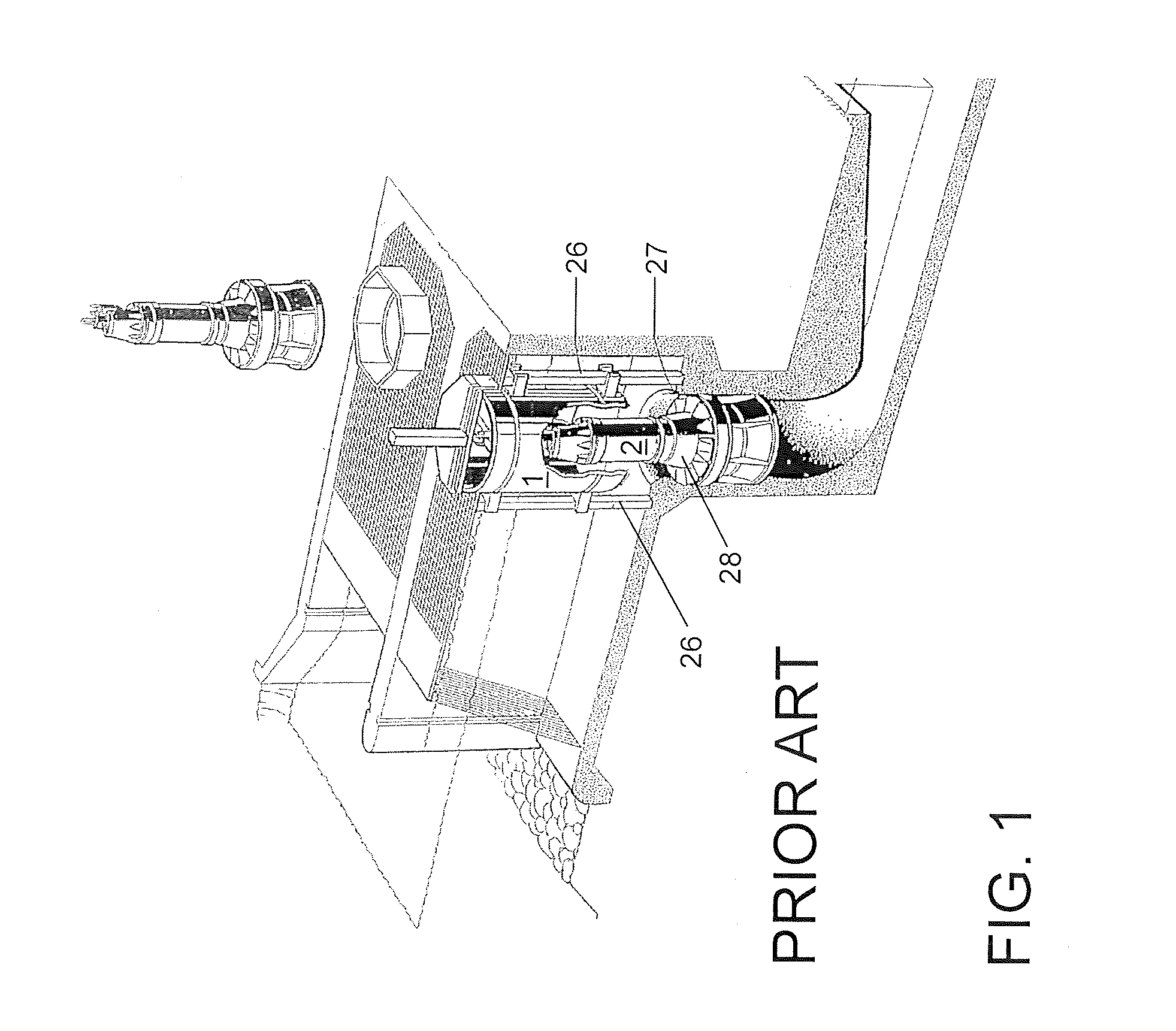
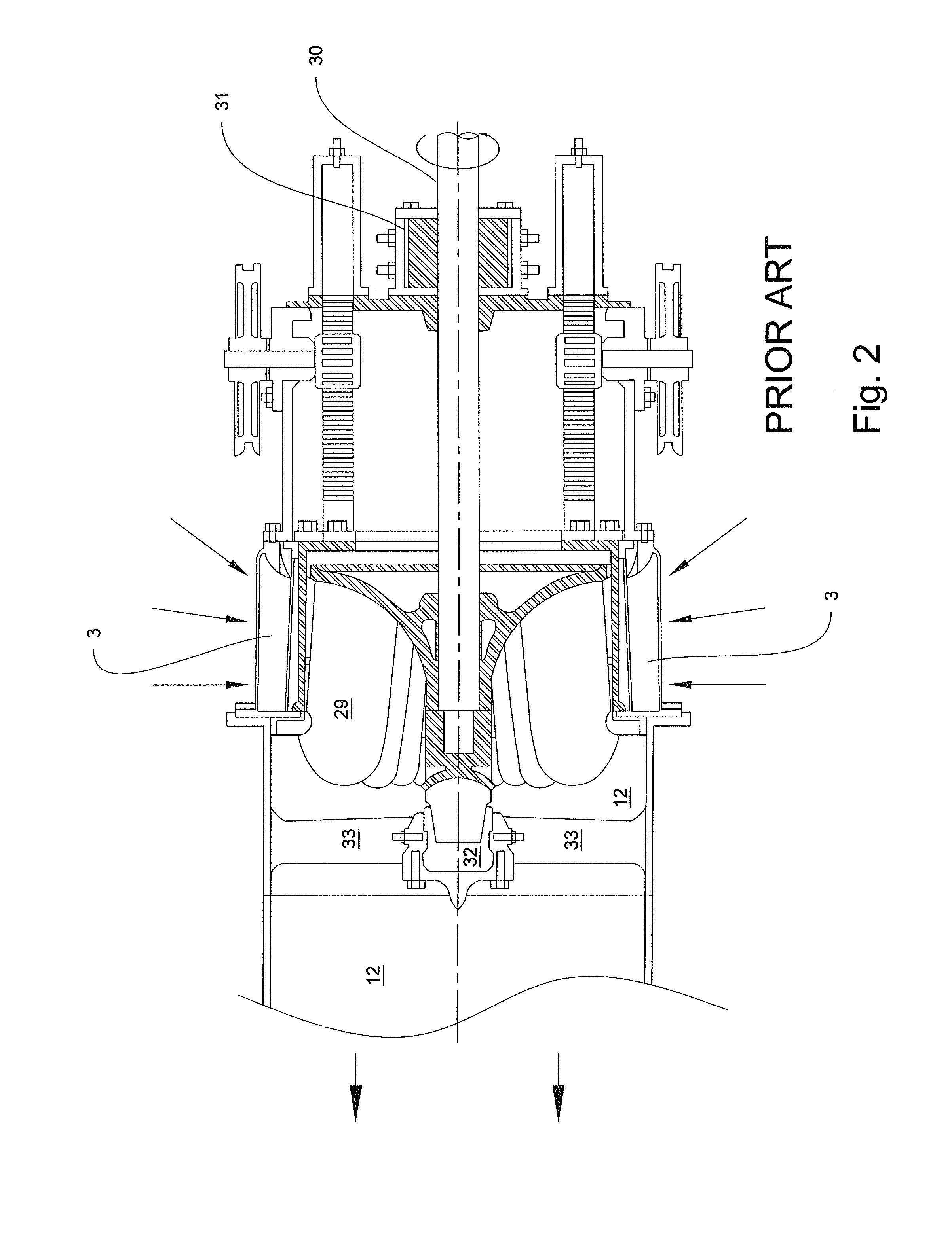
[0092]Referring to FIG. 1, a prior art turbine installation utilizing cylinder gates is shown. The illustrated prior art cylinder gates 1 are sized sufficiently large to allow complete removal of a hydroturbine-generator set through a closed cylinder gate 1. The large space between the cylinder gate 1 and the generator 2 housing outside diameter limits the use of such a cylinder gate 1 to vertical installations wherein the cylinder gate 1 extends above water level in its closed position. Furthermore, the configuration of the vertical guides 26 requires that they be positioned radially distant from the distributor inlet 27 in order to not cause unacceptable disturbance to the turbine inlet flow. The illustrated generator 2 housing outside diameter is too small for an economically designed direct drive generator, a gear speed increaser 28 thus being required. The gear speed increaser 28 generally results in a shorter turbine generator life with lower reliability compared to a direct d...


PUM


Abstract

Hydromotive machines, e.g. hydroturbines and pumps with integral low head loss shut off valves are described. Arrays of such hydroturbines facilitate power generation within the limited space available at pre-existing gated water control structures. An adjustable pitch hydroturbine runner particularly suited for use with the integral loss shut-off valve provides higher power output and higher specific speed than prior art hydroturbines at low head hydroelectric projects. Arrays of pumps in accordance with the present invention provide high discharge capacity in a limited space, with each individual pump within the array having an integral low head loss valve for shut off and backflow prevention.

Description

CROSS-REFERENCE TO RELATED APPLICATION[0001]The present application claims priority of U.S. Application No. 61 / 519,041 filed May 16, 2011.FIELD OF THE INVENTION[0002]The present invention relates to hydroelectric generating apparatus and water pumping apparatus and the method of constructing the same. More specifically this invention relates to retrofitting hydroelectric generating apparatus and to pre-existing gated water control structures originally constructed at navigation locks and dams and at water storage reservoirs where hydropower facilities were not originally installed and to fitting pump apparatus (especially for high volume storm water pumping) into limited space such as may be available in an urban area. The disclosed improvements in hydromotive machine shut-off and axial flow turbine runners have diverse applications for fluid conveyance and power generation, a few of many possible application examples being described herein.DESCRIPTION OF THE RELATED ART[0003]Hydrom...

Claims


Application Information

Patent Timeline
IPC IPC(8): F03B13/10F04D29/52
CPCF04D29/528F03B13/10F03B3/06F03B3/103F03B11/004F03B11/02F03B13/08F03B15/14Y02E10/20
Inventor OBERMEYER, HENRY
Owner OBERMEYER HENRY
Learn More