
Built-in refrigerator

a built-in refrigerator and refrigerator body technology, applied in the field of built-in refrigerators, can solve the problems of unsatisfactory solutions, marginal drop in the proportion of useable cooling chambers inside the carcass, and labor costs for installation of consumers which are not yet negligible, and achieve the effect of simplifying the adjustment of the cabin

Inactive Publication Date: 2012-04-24
BSH BOSCH & SIEMENS HAUSGERAETE GMBH
View PDF21 Cites 0 Cited by
  • Summary
  • Abstract
  • Description
  • Claims
  • Application Information

AI Technical Summary

Benefits of technology

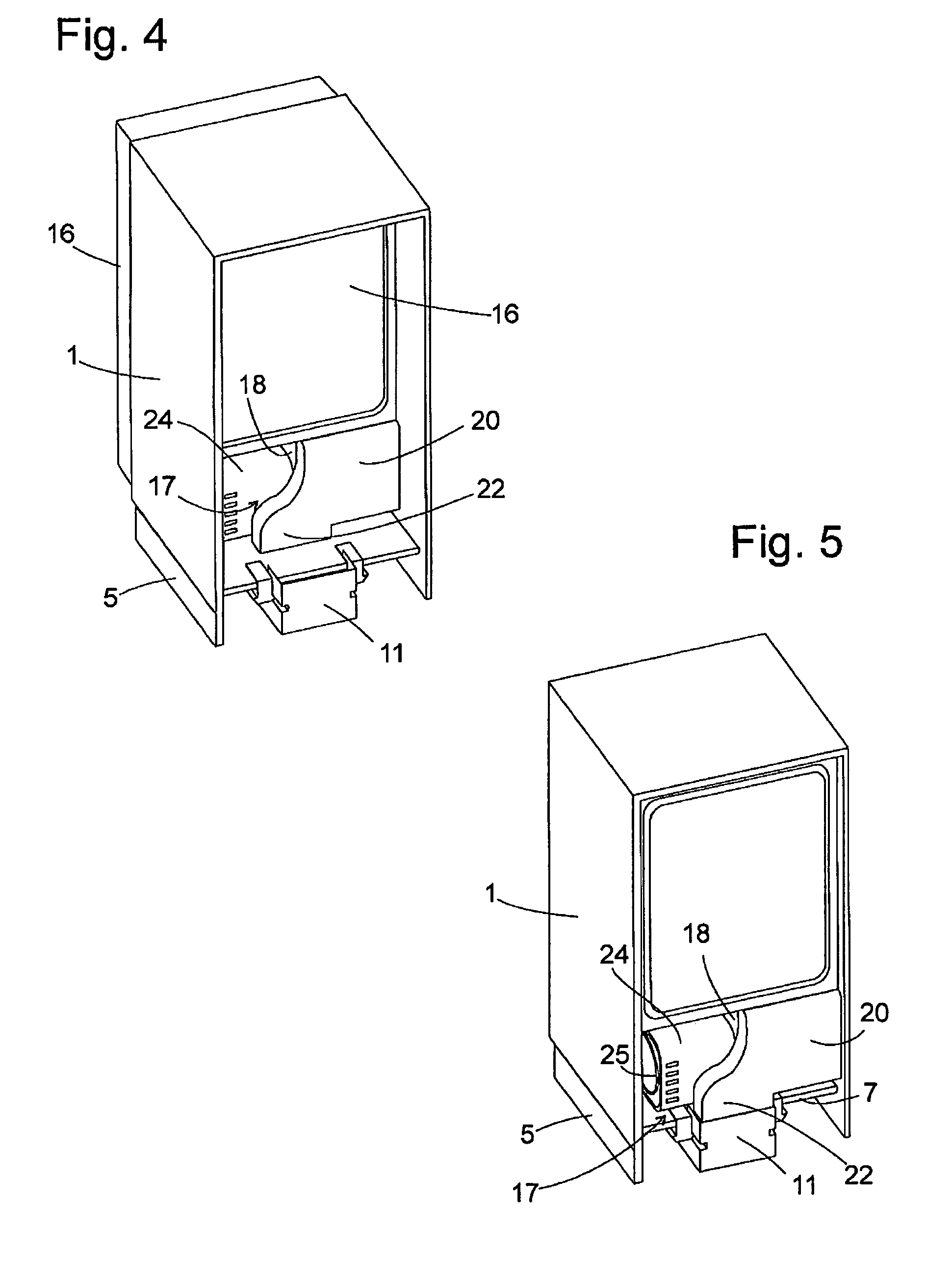
[0006]This delimitation suffices with a single opening in the base plate of the cabinet niche, through which both the inflow and also the outflow of cooling air for the machine compartment, the one via the passage delimited by the rear wall and the other outside the passage, can pass. It also allows the rear wall belonging to the carcass and independent of the cabinet to embody the flow channel for the cooling air at the level of the machine compartment with minimal projections and this to keep the flow resistance thereof as minimal as possible.
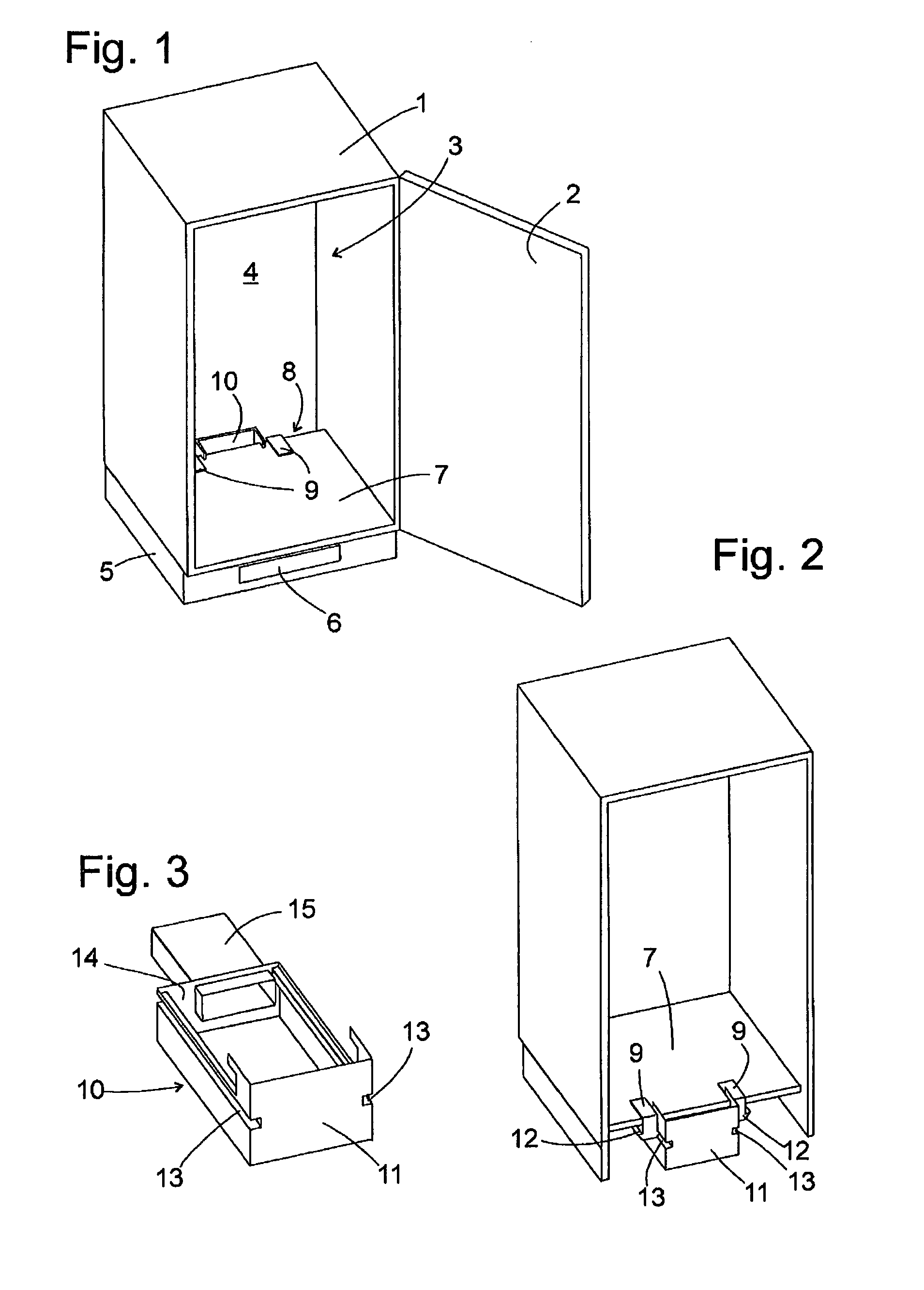
[0011]A simple and quicker assembly of the tray is enabled by means of guide rails, which can be assembled on an underside of the base plate of the niche in order to hold the tray to said underside.
[0012]An extensible tubular support of the tray can elongate the flow channel up to an opening formed in a front wall of the base region, without the dimensions of the tray having to be adjusted precisely to the depth of the base region. Flow channels for supply and discharged air can be guided in a precisely separate fashion up to this opening in the front wall.
[0014]If the carcass of the refrigerator is accommodated in a niche of a cabinet and the tray is accommodated in a base section of the cabinet, a gap is preferably provided between a base plate and a rear wall of the niche, via which the base section communicates with the niche and in which the first air passage and a second air passage are delimited from one another by means of the rear wall of the carcass. Only one single gap, instead of several separate openings in the base plate is thus needed to ventilate the machine compartment. This simplifies the adjustment of the cabinet to the refrigerator and is additionally advantageous in that a cabinet niche, which has already been used to accommodate a conventional refrigerator which is ventilated through the base region and via a flue on the rear side of the carcass, can essentially be used without the need for adjustment in order also to accommodate the inventive device.

Problems solved by technology

Since, if the carcass is incorporated into a cabinet niche, this machine compartment is countersunk deep into the niche, it is problematical to ensure adequate cooling of the units accommodated in the machine compartment by exchanging air with the environment.
Such a solution is unsatisfactory since it takes up considerable space in the machine compartment such that the proportion of useable cooling chamber inside the carcass drops marginally by comparison with the volume of the cabinet niche.
The two openings and the separating wall require the cabinet to be extensively adjusted to the refrigerator to be built-in, so that aside from the all the purchasing costs of the refrigerator, the consumer is also subjected to labor costs for the installation thereof which are not yet negligible.

Method used


Image

  • Built-in refrigerator
  • Built-in refrigerator
  • Built-in refrigerator

Examples


Embodiment Construction

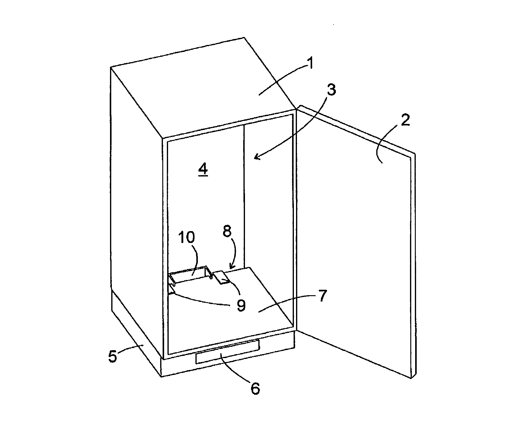
[0023]FIG. 1 shows a perspective view of a cabinet, which is provided in order to accommodate a built-in refrigerator. The cabinet has a square body 1, to which a door 2 is jointed and which delimits a built-in niche, which is provided in order to accommodate the carcass of the refrigerator. A rear wall 4 of the built-in niche can form part of the cabinet body 1, it could however also be formed by a wall of a building, in front of which the cabinet is mounted. The body 1 makes contact with a hollow base section 5, on the front side of which a ventilation opening 6 is formed. A gap 8 extends across the entire width of the built-in niche 3 between the rear wall 4 and the rear edge of a base plate 7 of the built-in niche 3.

[0024]Two holding clamps 9 of carrier sections which are concealed below the base plate 7 engage with the rear edge of the base plate 7 and, between the holding clamps 9, a rear section 10 of a tray 11 shown in detail in FIG. 3, said tray extending below the base pla...


PUM


Abstract

A built-in refrigerator comprising a carcass, in the lower rear area of which a machine compartment is formed. Said machine compartment is closed at least in part by means of a rear wall. The rear wall delimits a first air passage of the machine compartment at the level of a support area of the carcass.

Description

BACKGROUND OF THE INVENTION[0001]The present invention relates to a built-in refrigerator comprising a carcass, in the lower rear area of which a machine compartment is formed. Since, if the carcass is incorporated into a cabinet niche, this machine compartment is countersunk deep into the niche, it is problematical to ensure adequate cooling of the units accommodated in the machine compartment by exchanging air with the environment.[0002]One conventional approach to solving this problem is to embody a flue between a rear wall of the carcass and a rear wall of the cabinet niche, in which flue heated air can rise in the machine compartment, as a result of which cooling air is fed from below into the machine compartment. Such a solution is unsatisfactory since it takes up considerable space in the machine compartment such that the proportion of useable cooling chamber inside the carcass drops marginally by comparison with the volume of the cabinet niche.[0003]DE 199 33 603A1 discloses...

Claims


Application Information

Patent Timeline
Patent Type & Authority Patents(United States)
IPC IPC(8): F25D21/14
CPCF25B39/04F25D23/003F25D23/10F25D2323/00264F25D2323/00274
Inventor BENITSCH, ROLANDGRASY, SIEGFRIEDKUSNIK, THORSTENNUIDING, WOLFGANG
Owner BSH BOSCH & SIEMENS HAUSGERAETE GMBH
Learn More