Pivotally connected structure allowing lens replacement and lens angle adjustment
a technology of rotating connections and lens elements, applied in the direction of mountings, instruments, camera body details, etc., can solve the problems of large physical volume of elements, need to carry a plurality of lens elements around, and purchase of a plurality of lens elements is definitely more expensive than that of only the lenses, so as to achieve convenient portability and improve the effect of options
- Summary
- Abstract
- Description
- Claims
- Application Information
AI Technical Summary
Benefits of technology
Problems solved by technology
Method used
Image
Examples
Embodiment Construction
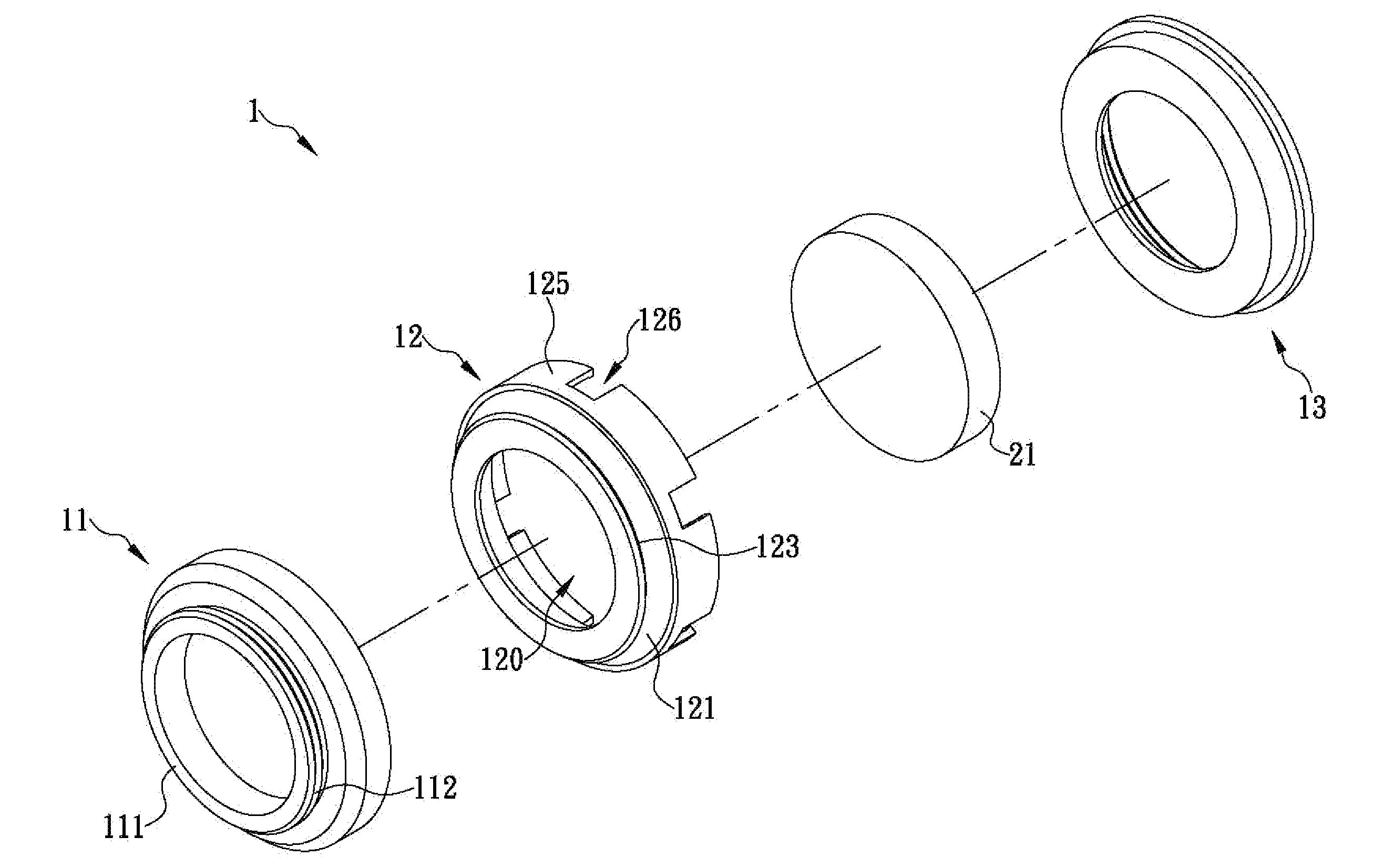
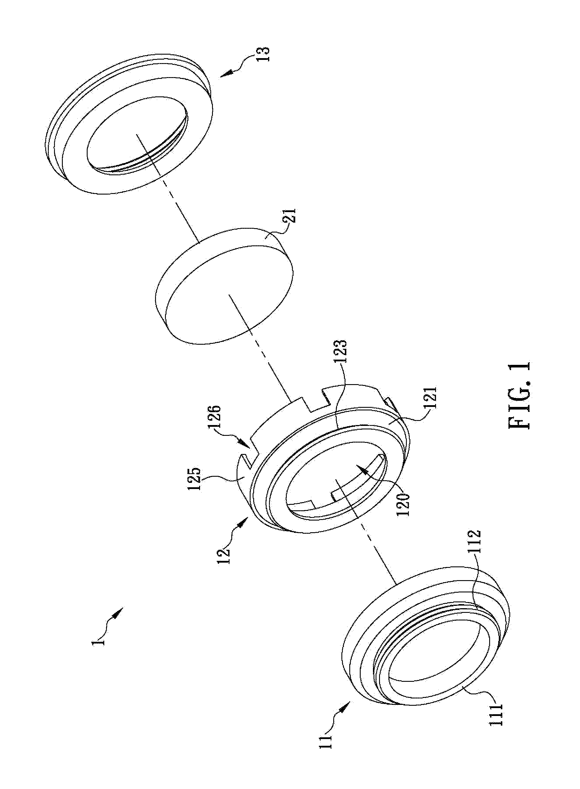
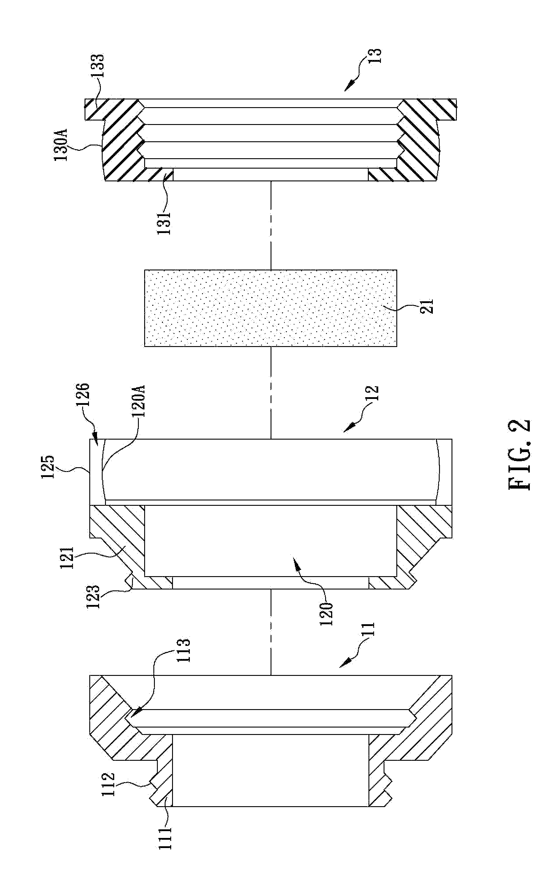
[0014]The present invention discloses a pivotally connected structure allowing lens replacement and lens angle adjustment. Referring to FIG. 1 and FIG. 2, the pivotally connected structure 1 includes a positioning frame 11, a pivotally connecting frame 12, and an engaging frame 13. In order for the pivotally connected structure 1 in this embodiment to be rapidly connectable to a camera lens 20 (see FIG. 3) and operate smoothly, the positioning frame 11, the pivotally connecting frame 12, and the engaging frame 13 are all hollow circular frames and are configured as follows. One end of the positioning frame 11 is provided with a positioning ring 111 which protrudes in an axial direction of the positioning frame 11. The outer periphery of the positioning ring 111 is provided with threads to be threadedly connected with threads 201 provided on the front side of the camera lens 20, thus allowing the positioning frame 11 to be positioned on the front side of the camera lens 20. The threa...
PUM
 Abstract
Description
Claims
Application Information
 - R&D
- Intellectual Property
- Life Sciences
- Materials
- Tech Scout
- Unparalleled Data Quality
- Higher Quality Content
- 60% Fewer Hallucinations
Browse by: Latest US Patents, China's latest patents, Technical Efficacy Thesaurus, Application Domain, Technology Topic, Popular Technical Reports.
© 2025 PatSnap. All rights reserved.Legal|Privacy policy|Modern Slavery Act Transparency Statement|Sitemap|About US| Contact US: help@patsnap.com


