
Collapsible Photovoltaic Module for a Large-Scale Solar Power Plant

a photovoltaic module and solar power technology, applied in photovoltaics, solar heat collectors for particular environments, heat collector mounting/support, etc., can solve the problems of high cost, high construction cost, and high electrical power requirements of traditional pv power plants, so as to improve the efficiency of incident light conversion to electrical power output of a particular pv-module, the effect of simple implementation

Active Publication Date: 2014-08-28
SUNTUBE HLDG APS
View PDF7 Cites 20 Cited by
  • Summary
  • Abstract
  • Description
  • Claims
  • Application Information

AI Technical Summary

Benefits of technology

The present invention aims to provide a way to build large-scale solar power plants that are materials and labor-efficient. Another object is to adjust the tilt angle of the solar panels to compensate for changes in the sun's path during different seasons, which improves the efficiency of converting light into electricity.

Problems solved by technology

The glass-content in these panels, which is on the order of 15-20 kg in a PV-module with a nameplate power of 200-300 W, makes them very heavy and expensive.
Furthermore, such conventional glass-plate PV-modules are rigid which places a practical upper limit on their size—and therefore also places upper limits to their electrical power.
A conventional PV power plant with a name plate power of 250 MW will therefore contain on the order of 1 million such PV-modules and an equally large number of connectors which is a source of reliability- and maintenance problems.
For these reasons, the traditional way to construct a PV power plant carries very high costs, due to high consumption of materials, such as glass in the PV-modules and steel in the racking hardware, cost of transportation to the deployment site, and the large amount of manual labour involved with the installation of the large number of small modules.
As a consequence, a PV power plant carries a large capital cost in its construction.
The first problem is that that they and their mounting hardware are heavy and contain large amounts of materials like glass, steel, aluminium and other structural materials compared to their electrical power.
The second problem is that the individual PV-modules are limited to a very low electrical power compared to typical generators on the electrical high-voltage power grid.
As a consequence, it is impractical to erect and maintain PV power plants of just a few hundred MW as they contain more than 1 million individual PV-modules.
Furthermore, since conventional glass-plate PV-modules cannot be scaled up because of transportation- and handling problems these rigid PV-modules are poorly suited for large-scale PV power plants.
This design is not suited for use in a large-scale solar power plant producing electricity to a power-grid.
The design of US 2001 / 0054252 A1 thus has a very sparse distribution of the actual active solar energy converters results in an ineffective utilisation of footprint which is incompatible with use in a large-scale solar power plant.
The disclosed PV-module is intended for floating deployment on a water surface and therefore inevitably requires a light weight structure with sufficient buoyancy to keep the PV-module afloat.

Method used


Image

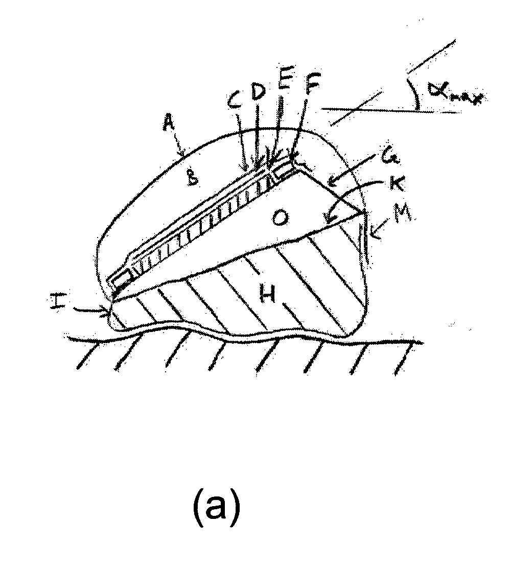
  • Collapsible Photovoltaic Module for a Large-Scale Solar Power Plant
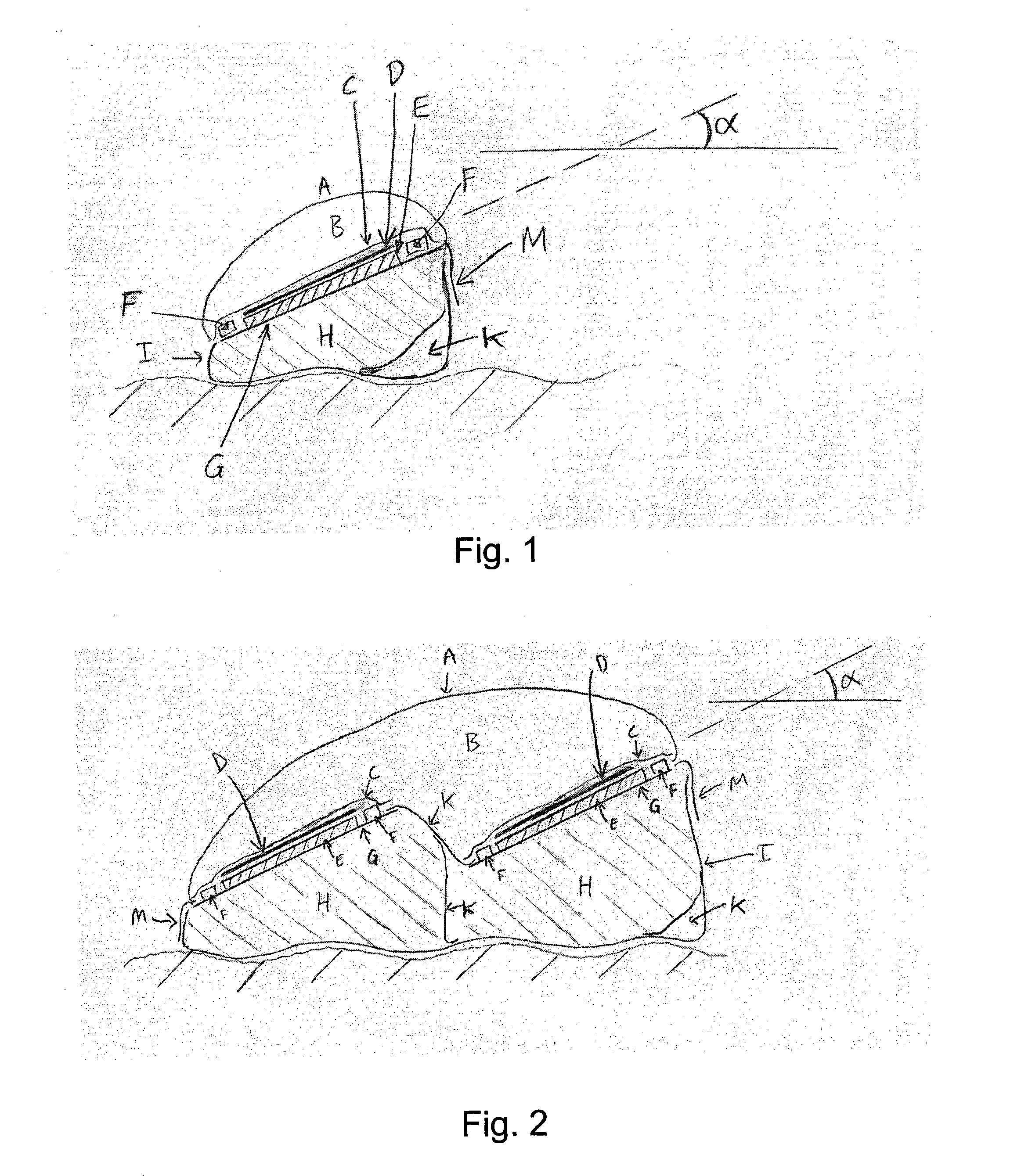
  • Collapsible Photovoltaic Module for a Large-Scale Solar Power Plant
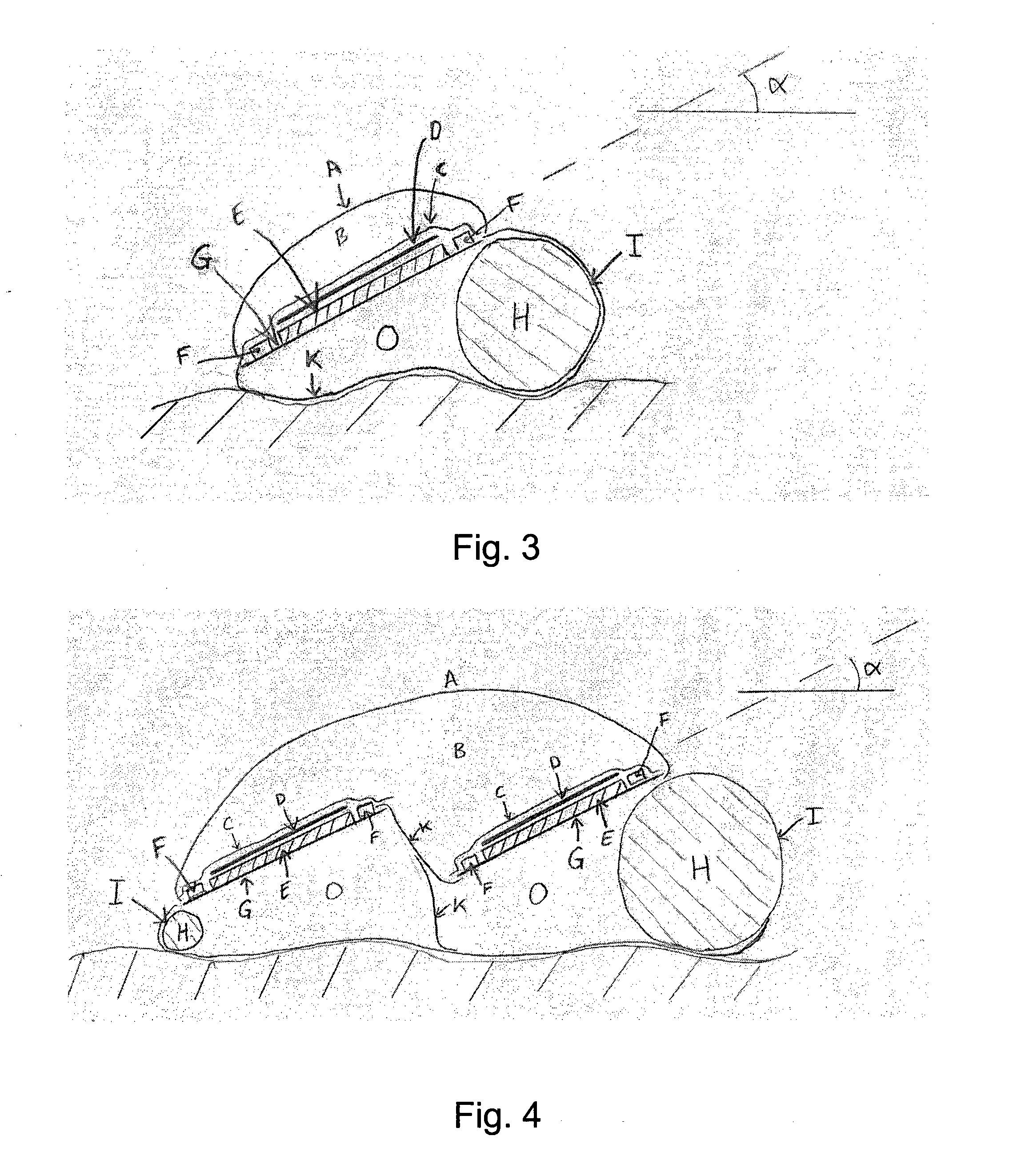
  • Collapsible Photovoltaic Module for a Large-Scale Solar Power Plant

Examples


example 1

[0095]If using industry-standard 6 inch by 6 inch c-Si PV-cells to fabricate PV-modules as described in this invention three 250 m long modules would be able to power the three (1 kV Uoc), 12 A (Isc)) inputs of a Danfoss string inverter model “Triple Lynx Pro 15 k” with more than 15 kW NOCT (Normal Operating Conditions and Temperature) —(or 17.6 kW STC (Standard Test Conditions)) which is ideal for this inverter. In this configuration the three PV-modules according to the present invention may replace a total of 72 traditional PV-modules of 220 W nominal power each. Up to 42 such inverters (thus fed by three PV-modules each) could then be coupled directly on an industry standard transformer (630 kW, 10 kV) for further connection within the PV power plant as described in the data sheet for the inverter [Danfoss Solar Inverters NS, Concept Paper, “String inverters for PV power systems” (2009)].


PUM

PropertyMeasurementUnit
electric poweraaaaaaaaaa
electrical poweraaaaaaaaaa
lengthaaaaaaaaaa

Abstract

An elongate photovoltaic (PV) module for use in a solar energy conversion plant for the production of electricity from incident light, the PV-module comprising a top portion with a support panel (G) carrying on a front side a plurality of electrically connected PV cells (D), and a transparent protective layer (A) sealed to the support panel (G) so as to encapsulate the PV-cells (D) between the support panel (G) and the protective layer (A), wherein prior to installation of the PV-module at the deployment site a collapsible portion of the PV-module is configured to be collapsible in a longitudinal direction by folding and / or rolling, wherein the collapsible portion includes at least the top portion, wherein the PV-module further comprises one or more integrated ballast chambers (I) in a bottom portion of the PV-module arranged on a rear side of the support panel (G), wherein said integrated ballast chamber (I) after installation of the PV-module at the deployment site contains an amount of a ballasting material (H) with a weight sufficient to immobilize the PV-module on a supporting surface of the deployment site under predetermined characteristic climate conditions for the deployment site.

Description

TECHNICAL FIELD[0001]The invention relates to an elongate photovoltaic (PV) module for use in a solar energy conversion plant for the production of electricity from incident light, the PV-module comprising a top portion with a support panel carrying on a front side a plurality of electrically connected PV cells, and a transparent protective layer sealed to the support panel so as to encapsulate the PV cells between the support panel and the protective layer, wherein prior to installation of the PV-module at the deployment site a collapsible portion of the PV-module is configured to be collapsible in a longitudinal direction by folding and / or rolling, wherein the collapsible portion includes at least the top portion.[0002]According to a further aspect, the invention relates to a method of installing a PV-module of the above-mentioned type.[0003]Throughout the present application, the term ‘photovoltaic’ is abbreviated by the acronym ‘PV’.BACKGROUND[0004]Solar power plants produce ele...

Claims


Application Information

Patent Timeline
Patent Type & Authority Applications(United States)
IPC IPC(8): H02S30/20H01L31/18
CPCH01L31/045H01L31/18H02S30/20H02S20/10Y02E10/47F24S20/80F24S25/10F24S2025/02Y10T29/49355Y02E10/50
Inventor VESBORG, PETER CHRISTIAN KJAERGAARD
Owner SUNTUBE HLDG APS
Learn More