
Foundation Apparatus and Method

Inactive Publication Date: 2014-08-28
SHANER IND
View PDF24 Cites 10 Cited by
  • Summary
  • Abstract
  • Description
  • Claims
  • Application Information

AI Technical Summary

Benefits of technology

The present invention is a foundation apparatus, a method of providing structural support, and a method of making, using, and installing the foundation apparatus for structural support. The foundation apparatus eliminates the need for specialized installation equipment and reduces expenses associated with excavation, placing of concrete reinforcing rods, trucking, and time delay. This patent addresses the technical problem of providing a foundation that is efficient, cost-effective, and easy to install.

Problems solved by technology

A disadvantage of the replacement pile is that the excavated material must be collected and removed from the construction site.
Disadvantages associated with displacement pile foundations include the tendency to deviate when obstructions are encountered underground and the potential for difficult installation in dense soil conditions.
Additionally, foundations supporting specialized structures such as solar panel heliostats are subject to lateral loads and bending moments where lateral and rotational deflections must be limited to values much lower than is permitted for typical building structures.
In order to accommodate tolerable deflection limits for these and other specialized structures, typical steel pile foundations and precast pile foundations need to have cross-sectional geometric properties that make them prohibitively large, expensive, and time consuming to construct.

Method used


Image

  • Foundation Apparatus and Method
  • Foundation Apparatus and Method
  • Foundation Apparatus and Method

Examples


Embodiment Construction

[0034]In the following discussion of the non-limiting embodiments of the invention, spatial or directional terms, such as “inner”, “outer”, “up”, “down”, and the like, relate to the invention as it is shown in the drawing figures. However, it is to be understood that the invention can assume various alternative orientations and, accordingly, such terms are not to be considered as limiting. Further, in the discussion of the non-limiting embodiments of the invention, it is understood that the invention is not limited in its application to the details of the particular non-limiting embodiments shown and discussed since the invention is capable of other embodiments.

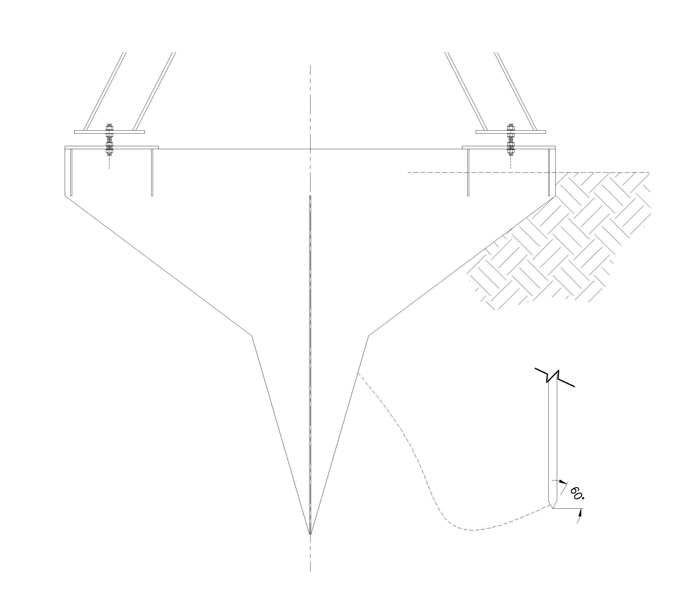
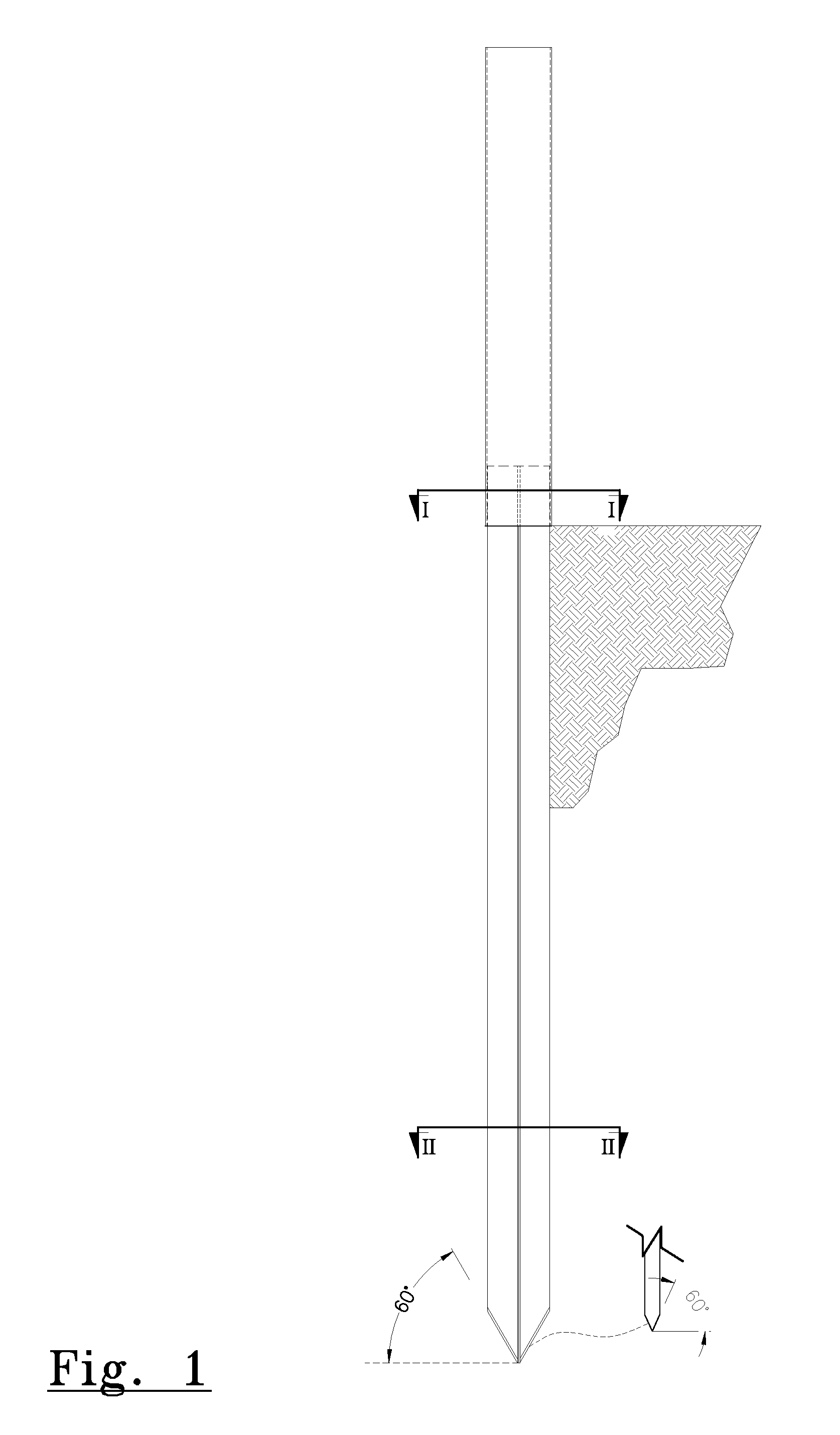
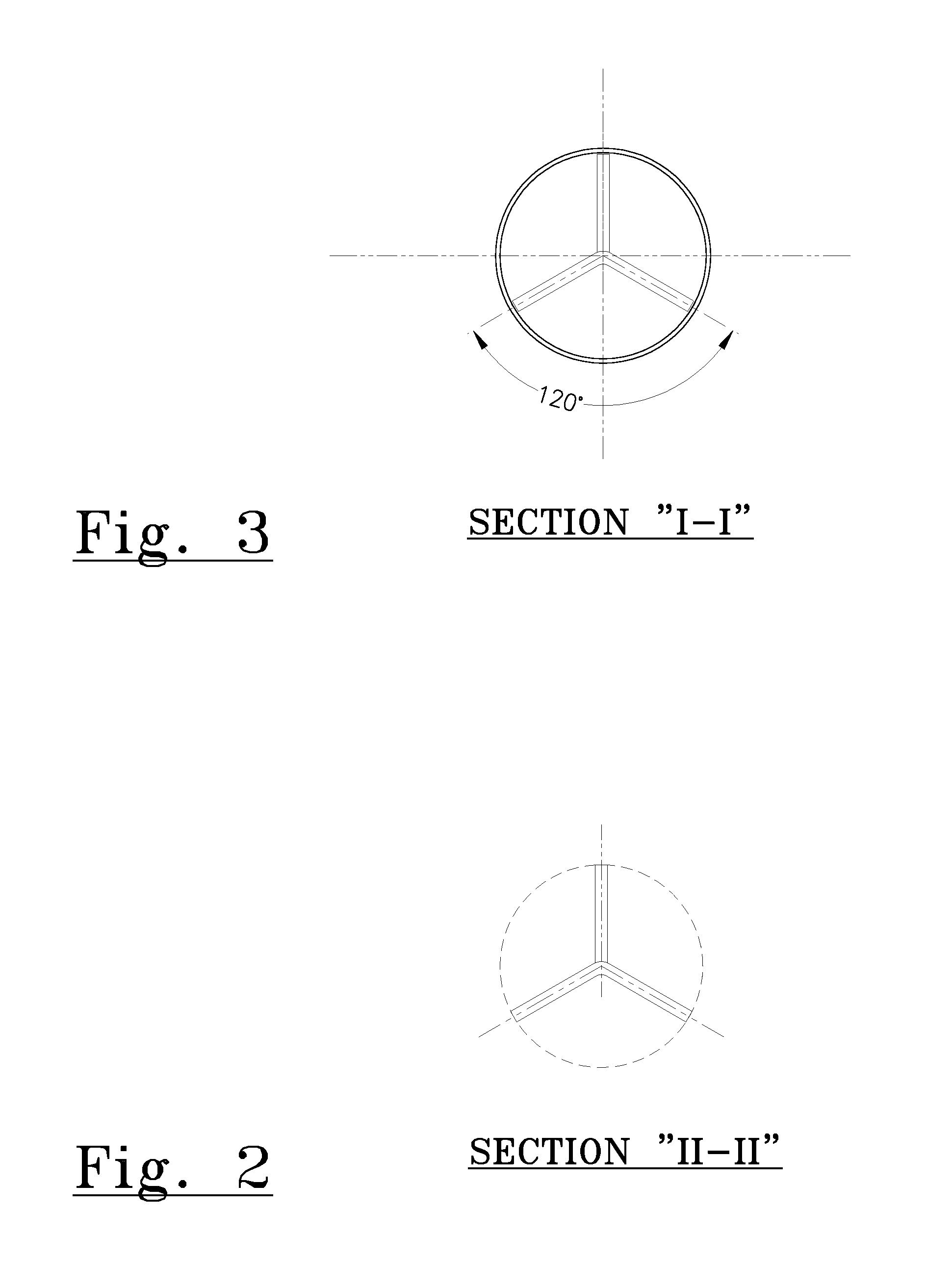
[0035]FIGS. 1-3 illustrate a foundation apparatus for supporting and anchoring a ground-supported structure according to an embodiment of the present invention. The foundation apparatus extends longitudinally along a central axis. The ground-engaging portion of the foundation apparatus is adapted to be inserted into the groun...


PUM


Abstract

A foundation apparatus comprised of flat plates that is used to support above-ground structures is disclosed. A method of making, using and installing a pile foundation for those applications is also provided. The present invention relates to various flat plate foundation supports that provide a foundation anchor for various ground supported structures. Specifically, the present invention relates to a foundation anchor support that comprises flat longitudinally extending plates that are adapted to be inserted beneath a ground surface.

Description

CROSS REFERENCE TO RELATED APPLICATIONS[0001]The present invention claims the benefit of U.S. Provisional Application No. 61 / 537,803, filed 22 Sep. 2011, U.S. Provisional Application No. 61 / 671,469, filed 13 Jul. 2012, and U.S. Provisional Application No. 61 / 671,488, filed 13 Jul. 2012.TECHNICAL FIELD[0002]The present invention relates to a pile foundation used to support structures or stabilize slopes and further relates to a method of making, using and installing a pile foundation for those applications. The present invention relates to foundation apparatus that provides a foundation anchor for various ground supported structures. Specifically, the present invention relates to a foundation anchor support that comprises flat longitudinally extending plates that are adapted to be inserted beneath a ground surface.BACKGROUND ART[0003]U.S. Pat. Nos. 4,882,891 and 4,974,997 are both assigned to the Assignee of the current application and disclose a foundation apparatus and a foundation...

Claims


Application Information

Patent Timeline
IPC IPC(8): E02D27/12
CPCE02D27/12E02D5/80E02D27/02E02D27/32E02D27/50B21D47/00E02D5/28E02D7/18E02D13/04E02D27/42E04H12/2215
Inventor KRONZ, WILLIAM MARTINSCHULER, MICHAEL FRANCISLUIDELLI, DAVIDEREINERT, GARY J.
Owner SHANER IND
Learn More