Field replaceable power supply cartridge

a technology of power supply cartridges and replacement parts, which is applied in the direction of electrical apparatus casings/cabinets/drawers, coupling device connections, instruments, etc., can solve the problems of power supply failure, difficult and time-consuming replacement, and prolonging the process, so as to facilitate the coupling of the led driver and facilitate the installment of the led driver

Active Publication Date: 2014-08-21
KORRUS INC
View PDF43 Cites 18 Cited by
  • Summary
  • Abstract
  • Description
  • Claims
  • Application Information

AI Technical Summary

Benefits of technology

The present invention provides a field replaceable power supply cartridge for LED drivers that can be easily connected to a socket. The cartridge has a latch mechanism and a key feature that allows for only one orientation of connection to the socket to prevent incorrect electrical connection. The cartridge also has a multi-pin electrical connector for coupling with a corresponding connector on the socket, which allows for a thermal connection as well. The invention also provides a printed circuit board and one or more gripping members that can actuate the latches for easy installation. The key feature on the cartridge body and the key portion on the socket body facilitate the coupling of the cartridge to the socket in a single predetermined orientation.

Problems solved by technology

Power supplies fail over time, for example, due to the exposure of the electronics to heat generated by the lighting system.
One drawback with conventional power supplies is that they can be difficult and time consuming to replace because of the limited access space through the ceiling opening where the recessed down light is mounted.
Because all of this is done through the limited space provided by the ceiling aperture for the recessed down light, a user has to perform all of these steps with a single hand, which makes the process take longer, particularly because of all the different parts and steps that are involved in replacing the power supply.
And in most cases the user cannot see the power supply within the recessed down light, and therefore has to remove and replace the fasteners without a line of sight to the power supply assembly while performing these steps.

Method used


Image

  • Field replaceable power supply cartridge
  • Field replaceable power supply cartridge
  • Field replaceable power supply cartridge

Examples


Embodiment Construction

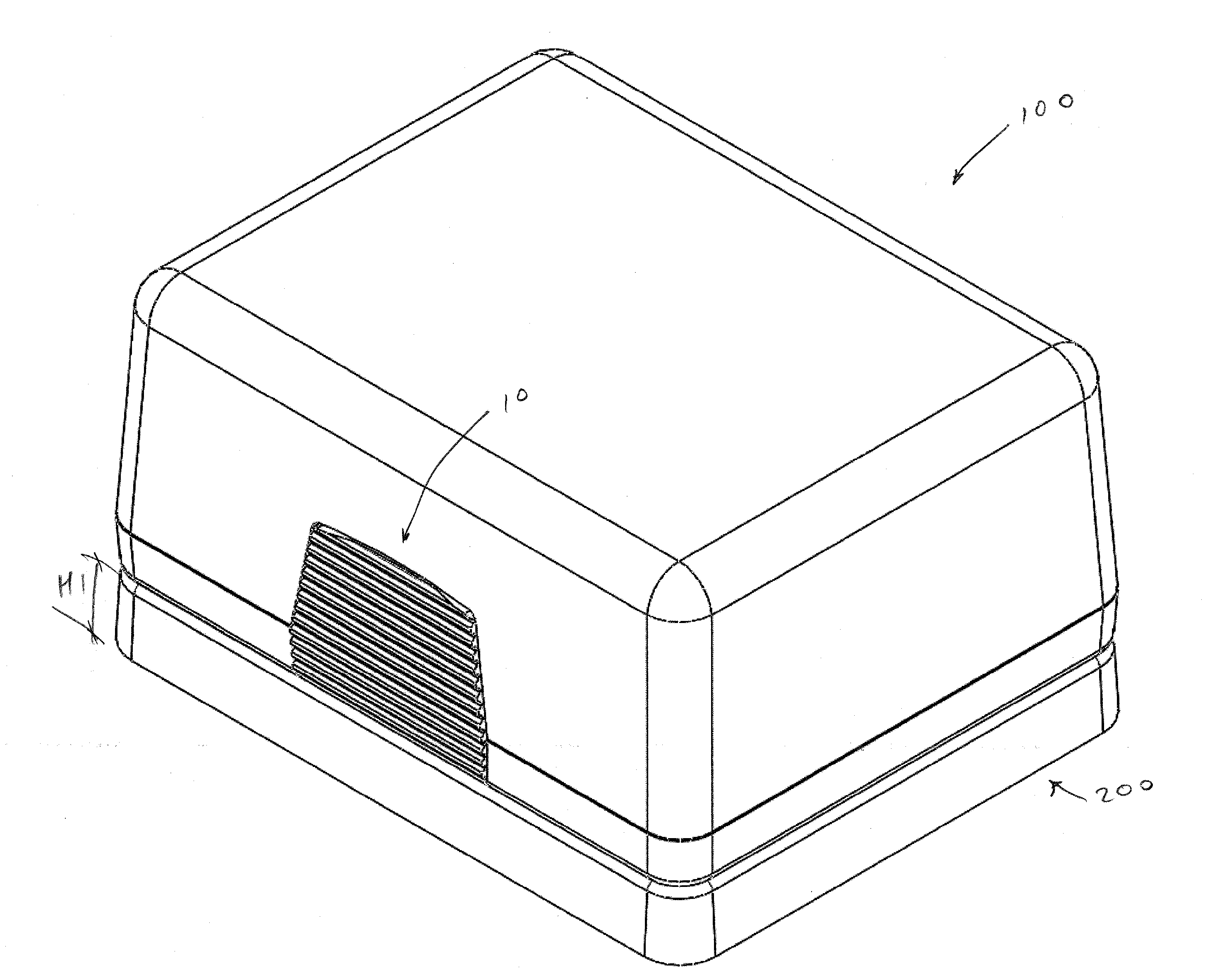
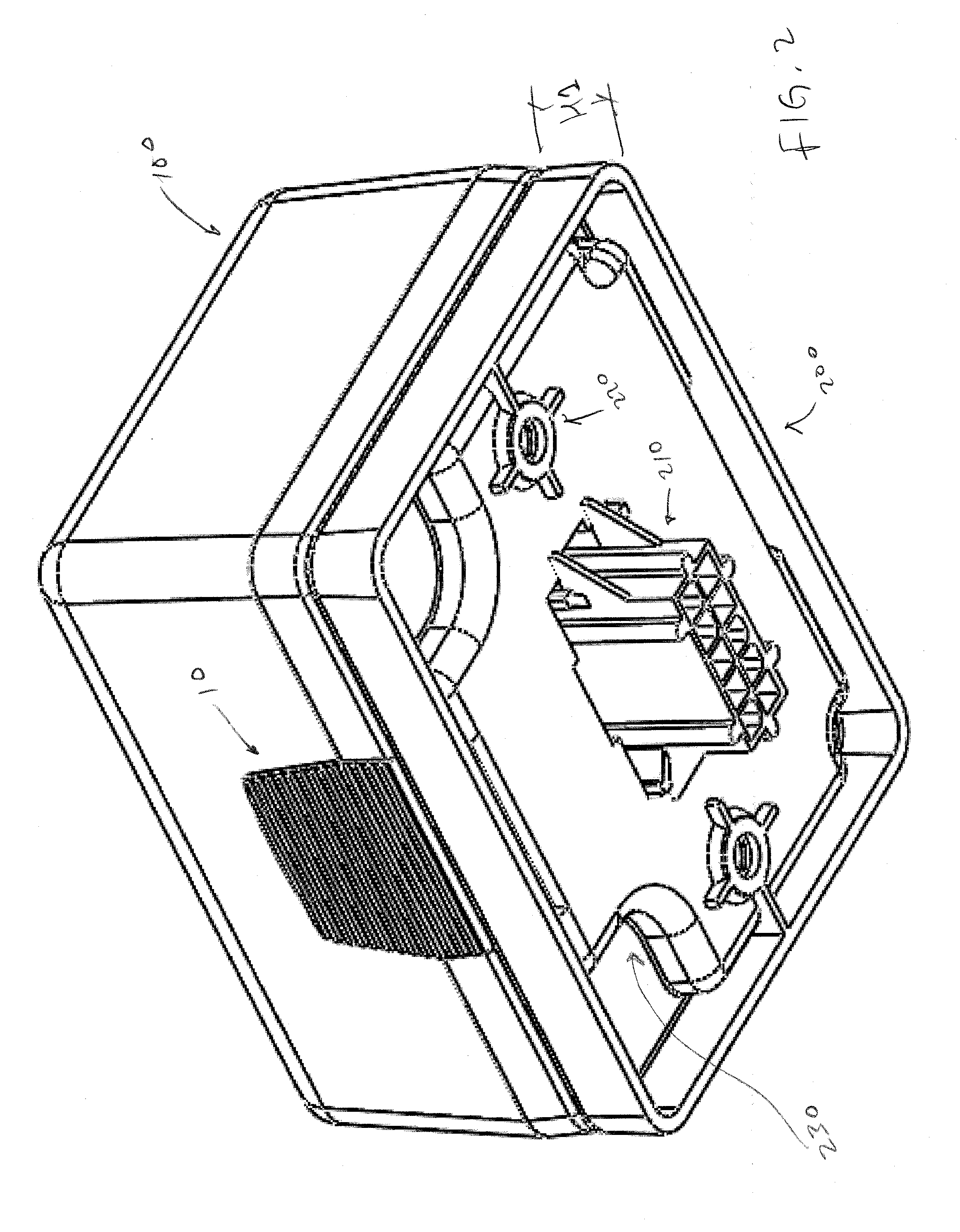
[0026]The embodiments disclosed below describe an improved system and method for a field replaceable power supply cartridge. In one embodiment, the field replaceable power supply cartridge can be an LED driver cartridge, such as a replaceable LED driver cartridge for use with down lighting (e.g., recessed lighting) systems. In another embodiment, the field replaceable power supply cartridge can be a ballast, such as a ballast for a fluorescent lighting system, a ballast for a compact fluorescent lighting system, a ballast for an HID (high intensity discharge) lighting system, or used in connection with any other light source or lighting system that uses a power supply or ballast. In another embodiment, the field replaceable power supply cartridge can be an LED driver cartridge for use within an LED light fixture assembly. In still another embodiment, the field replaceable power supply cartridge can be a transformer (e.g., step down transformer).

[0027]One of skill in the art will rec...


PUM


Abstract

A field replaceable power supply cartridge is provided for coupling with a socket. The cartridge has a latch mechanism that can be actuated by the user to couple the cartridge to the socket, such that latches of the cartridge releasably engage recessed portions in the socket. The cartridge has a key feature that corresponds to a key feature on the socket, allowing the cartridge to be coupled to the socket in only one orientation, thereby preventing the incorrect electrical connection between the cartridge and the socket. The cartridge can have a multi-pin electrical connector for coupling to a corresponding connector on the socket. The socket can be a relatively short socket, where the electrical wires are bottom fed, or can be a relatively tall socket, where the electrical wires are side fed via one or more openings in the body of the socket.

Description

INCORPORATION BY REFERENCE TO ANY PRIORITY APPLICATIONS[0001]Any and all applications for which a foreign or domestic priority claim is identified in the application Data Sheet as filed with the present application are hereby incorporated by reference under 37 CFR 1.57. This application claims the benefit of U.S. Provisional Application No. 61 / 765257, filed Feb. 15, 2013 and titled FIELD REPLACEABLE POWER SUPPLY CARTRIDGE, the entirety of which is incorporated by reference and should be considered a part of this specification.BACKGROUND[0002]1. Field[0003]The invention is directed to a field replaceable power supply cartridge and more particularly to a field replaceable power supply cartridge for use within lighting fixture assemblies.[0004]2. Description of the Related Art[0005]There are many different electric lighting technologies, which all require a power supply, a transformer or a ballast (e.g., LED, HID, Compact Fluorescent, linear fluorescent, low-voltage halogen, etc.). All...

Claims


Application Information

Patent Timeline
IPC IPC(8): H05K7/10
CPCH05K7/10F21H1/00G02B6/00H05K7/1455F21V29/67F21Y2115/10F21S8/026H01R12/7088H01R13/6271H01R13/64H01R13/6675H05K5/0026H05K5/0221H05K5/0286
Inventor ALEXANDER, CLAYTON
Owner KORRUS INC
Why Eureka
Try Eureka