
Structure and method for compensating temperature dependent magnification and focus change

a technology of temperature dependence and compensation structure, applied in the field of ambient temperature compensation structure and method for compensating temperature dependent magnification and focus change of lens device, can solve problems such as the rise of ambient temperature of projector

Inactive Publication Date: 2014-08-21
BARCO NV
View PDF3 Cites 9 Cited by
  • Summary
  • Abstract
  • Description
  • Claims
  • Application Information

AI Technical Summary

Benefits of technology

The invention is a structure that can be easily operated by an unskilled operator and is very convenient to use. It is modular and can be applied to any optical device with a lens. The ambient temperature compensation element can be easily replaced in case of malfunctioning, which offers a great advantage compared to prior art where entire lens barrels of images devices have been replaced.

Problems solved by technology

However, when using projectors due to the extreme temperature of its light source it causes the ambient temperature of the projector to rise.

Method used


Image

  • Structure and method for compensating temperature dependent magnification and focus change
  • Structure and method for compensating temperature dependent magnification and focus change
  • Structure and method for compensating temperature dependent magnification and focus change

Examples


Embodiment Construction

[0030]The present invention will be described with respect to particular embodiments and with reference to certain drawings but the invention is not limited thereto but only by the claims. The drawings described are only schematic and are non-limiting. In the drawings, the size of some of the elements may be exaggerated and not drawn on scale for illustrative purposes. Where the term “comprising” is used in the present description and claims, it does not exclude other elements or steps. Where an indefinite or definite article is used when referring to a singular noun e.g. “a” or “an”, “the”, this includes a plural of that noun unless something else is specifically stated.

[0031]The term “comprising”, used in the claims, should not be interpreted as being restricted to the means listed thereafter; it does not exclude other elements or steps. Thus, the scope of the expression “a device comprising means A and B” should not be limited to devices consisting only of components A and B. It ...


PUM


Abstract

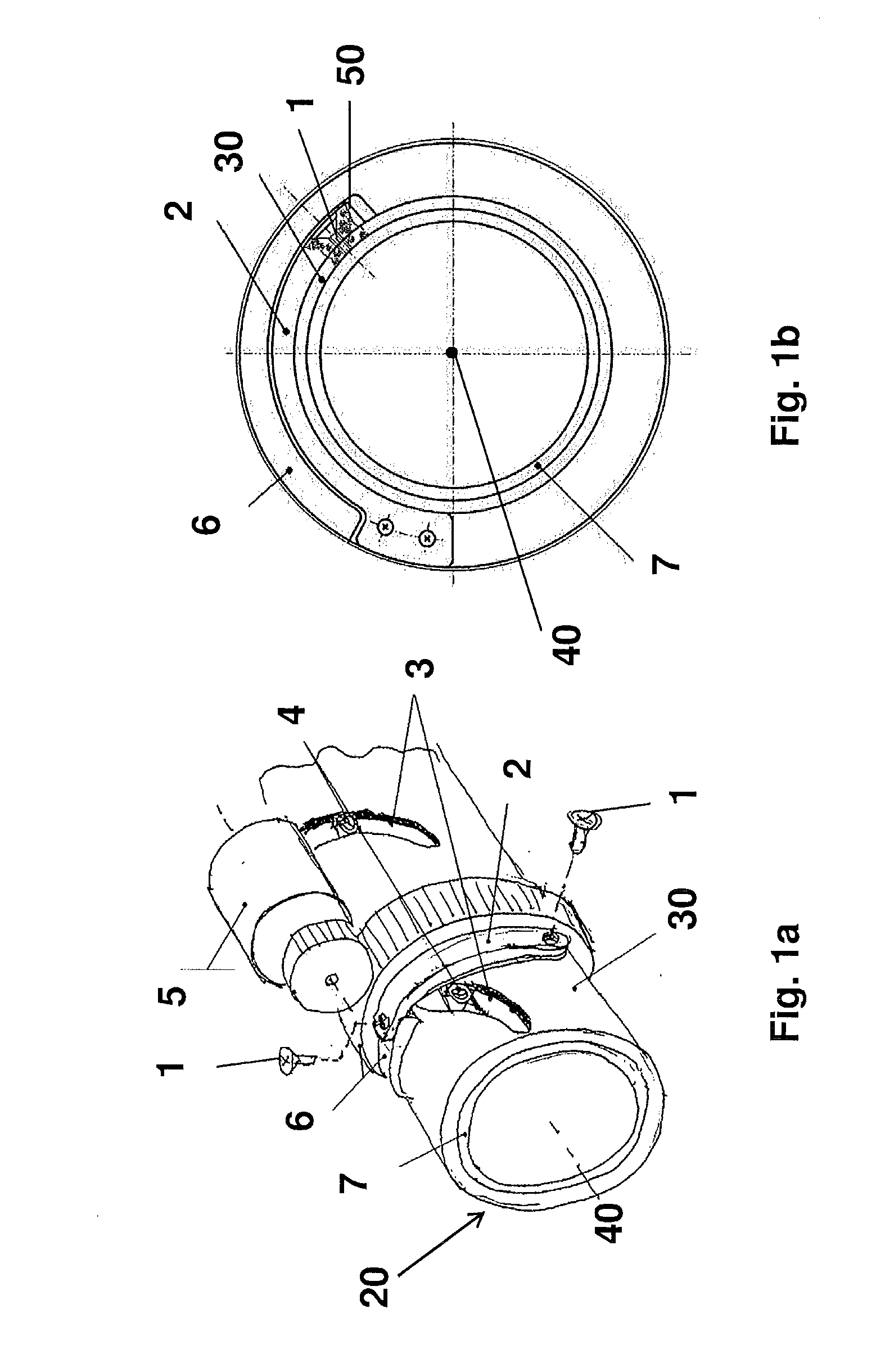
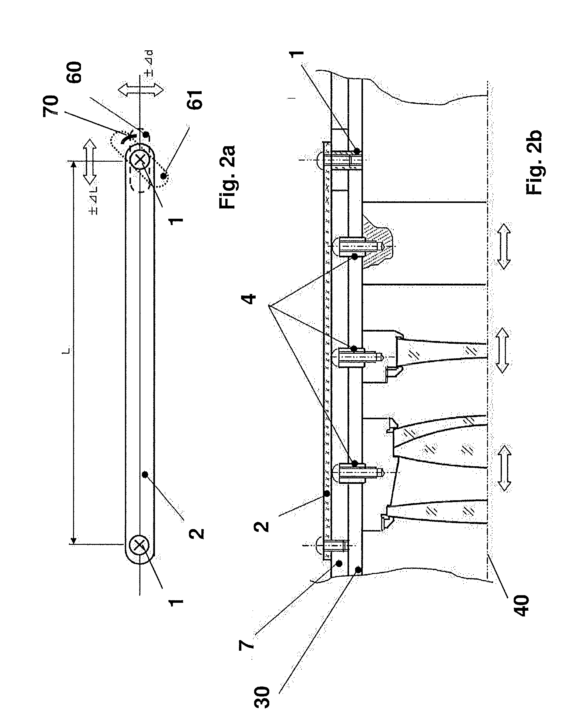
A method and device is described for compensating ambient temperature dependent magnification and focus change of a zoom lens system, whereby an ambient temperature compensation structure cooperates with a rotational ring and an optical-element adjusting member such that a phase variation between the rotational ring and the optical-element adjusting member in response to an ambient temperature change is compensated and whereby the phase variation characterizes an optical property of the zoom lens system such as magnification or focus.

Description

FIELD OF THE INVENTION[0001]The present invention relates to an ambient temperature compensation structure and method for compensating temperature dependent magnification and focus changes of a lens device.BACKGROUND OF THE INVENTION[0002]Projection lenses are designed so as to come into focus at a predetermined image formation position at room temperature. However, when using projectors due to the extreme temperature of its light source it causes the ambient temperature of the projector to rise. As a result, because the lens elements have a temperature dependency on refractive indices, radiuses of surfaces and thickness, the optical power changes accordingly to the elevated ambient temperature. For instance, after switching a projector on, the focus on the screen gradually changes and the best focus plane is moved to backside of the screen (1.2 m) and the image on the screen becomes blurred.[0003]U.S. Pat. No. 6,144,510 describes thermal compensation system for an optical lens that...

Claims


Application Information

Patent Timeline
Patent Type & Authority Applications(United States)
IPC IPC(8): G02B7/02G02B7/10
CPCG02B7/10G02B7/028G02B15/00
Inventor NAKANO, HIROMITSULAMBOT, DANIELVAN BELLE, KOEN
Owner BARCO NV
Learn More