Phase modulation apparatus
a phase modulation and apparatus technology, applied in the direction of electrical apparatus, instruments, optics, etc., can solve the problems of significant deterioration of transmission characteristics, waveform becomes distorted, transmission characteristics are significantly deteriorated, etc., and achieve the effect of simplifying the phase control circuit and miniaturizing the phase modulation apparatus
- Summary
- Abstract
- Description
- Claims
- Application Information
AI Technical Summary
Benefits of technology
Problems solved by technology
Method used
Image
Examples
first embodiment
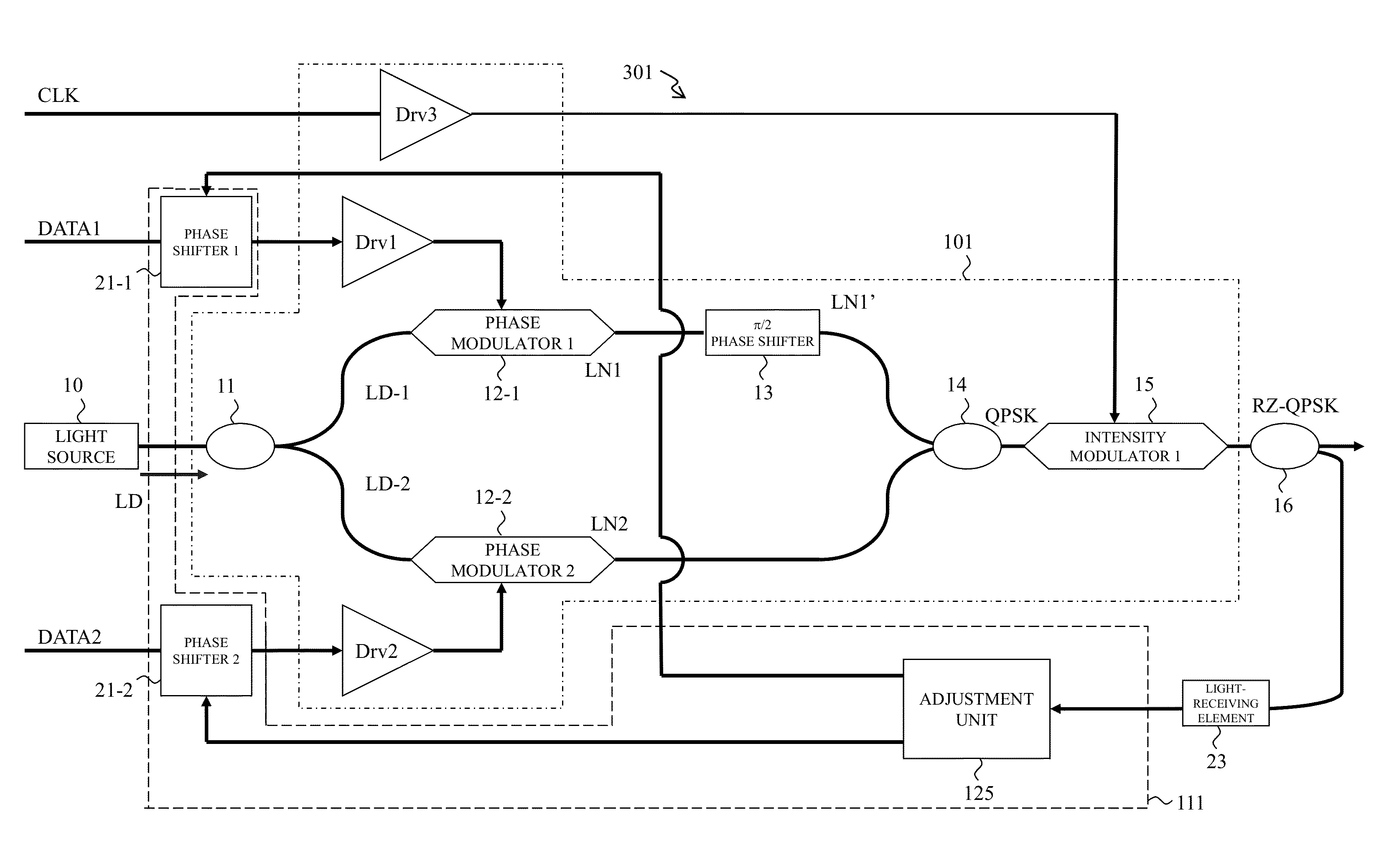
[0034]FIG. 6 is a view for explaining a phase modulation apparatus 301 as an example of the present embodiment. The phase modulation apparatus 301 is provided with an RZ phase modulation circuit 101 and a phase control circuit 111. The RZ phase modulation circuit 101 has a light source 10 outputting continuous light and two phase modulators (12-1, 12-2) and an intensity modulator 15. The phase modulators (12-1, 12-2) phase-modulates the continuous light from the light source 10 based on data signals (DATA1, DATA2) input to each phase modulators and generate two phase modulation optical signals. A phase shifter 13 shifts one phase of the phase modulation optical signal by π / 2 and generates a quadrature phase modulation signal combined with the other phase modulation optical signal. An intensity modulator 15 intensity-modulates the quadrature phase modulation signal with a clock signal CLK synchronized with the data signal to convert the signal into an RZ signal, and, thus, to output ...
second embodiment
[0039]FIG. 9 is a view for explaining a phase modulation apparatus 302 as an example of the present embodiment. The phase modulation apparatus 302 mounts an example of a configuration of the adjustment unit 125 described in the phase modulation apparatus 301 of FIG. 6.
[0040]A phase control circuit 111 has a pilot signal supplying portion 22 which performs pilot signal superimposition in which a pilot signal having a predetermined frequency is superimposed on a control signal J indicating the phase shift amount in which phase shifters (21-1, 21-2) shift the phase of a data signal and the phase shift amount is oscillated with a predetermined frequency, a synchronous detecting portion 24 which performs synchronous detection of an electrical signal, to which the output of the intensity modulator 15 is optical-electrically converted, with the same frequency as the pilot signal, and an adjustment portion 25 which performs adjustment operation in which the control signal J of the phase shi...
third embodiment
[0051]FIG. 12 is a view for explaining a phase modulation apparatus 303 of the second embodiment. The phase modulation apparatus 303 is different from the phase modulation apparatus 302 of FIG. 9 in that a phase control circuit 112 is provided instead of the phase control circuit 111. The phase control circuit 112 and the phase control circuit 111 are different in the number of the pilot signals. The phase modulation apparatus 303 performs the skew adjustment with a single pilot signal having a frequency f. More specifically, the skew adjustment of the phase modulation optical signal LN1 and the skew adjustment of the phase modulation optical signal LN2 are performed while shifting the time. Thus, the phase modulation apparatus 303 has in the phase control circuit 112 a switching switch 26 switching the output destination of the pilot signal. The skew adjustment method is similar to the skew adjustment method in the phase modulation apparatus 302 described in FIGS. 10 and 11.
PUM
| Property | Measurement | Unit |
|---|---|---|
| optical phases | aaaaa | aaaaa |
| optical phase | aaaaa | aaaaa |
| phase | aaaaa | aaaaa |
Abstract
Description
Claims
Application Information
 - R&D
- Intellectual Property
- Life Sciences
- Materials
- Tech Scout
- Unparalleled Data Quality
- Higher Quality Content
- 60% Fewer Hallucinations
Browse by: Latest US Patents, China's latest patents, Technical Efficacy Thesaurus, Application Domain, Technology Topic, Popular Technical Reports.
© 2025 PatSnap. All rights reserved.Legal|Privacy policy|Modern Slavery Act Transparency Statement|Sitemap|About US| Contact US: help@patsnap.com


