
Elongate medical device handle autolock

a technology for medical devices and handles, applied in the field of elongated medical devices, can solve the problems of the distal end of the device deflecting, and achieve the effect of reducing the weight and/or the cost of a traditional catheter

Active Publication Date: 2014-08-14
ST JUDE MEDICAL ATRIAL FIBRILLATION DIV
View PDF9 Cites 15 Cited by
  • Summary
  • Abstract
  • Description
  • Claims
  • Application Information

AI Technical Summary

Benefits of technology

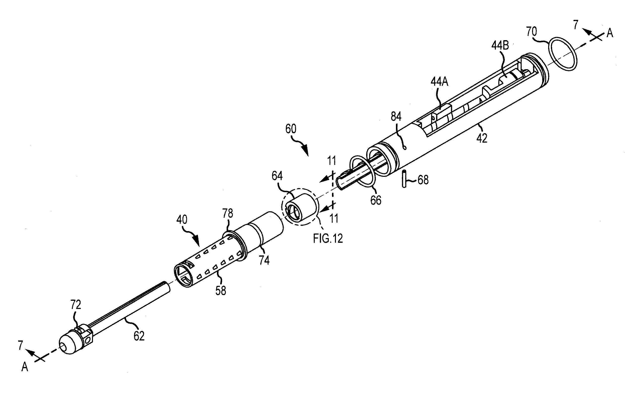
The handle assembly for a catheter described in this patent may make the traditional catheter handle lighter and less expensive. It includes an adjusting knob, an insert, and a dowel pin. The insert is connected to the adjusting knob and can rotate around the axis. The insert has a chamfered sidewall and a plastic or polymer material. The dowel pin prevents the insert from rotating. Overall, this handle assembly simplifies the procedure of catheter use and reduces the risk of complications.

Problems solved by technology

Placing a pull wire in tension may cause the distal end of the device to deflect in at least one plane.

Method used


Image

  • Elongate medical device handle autolock
  • Elongate medical device handle autolock
  • Elongate medical device handle autolock

Examples


Embodiment Construction

[0028]Various embodiments are described herein to various apparatuses, systems, and / or methods. Numerous specific details are set forth to provide a thorough understanding of the overall structure, function, manufacture, and use of the embodiments as described in the specification and illustrated in the accompanying drawings. It will be understood by those skilled in the art, however, that the embodiments may be practiced without such specific details. In other instances, well-known operations, components, and elements have not been described in detail so as not to obscure the embodiments described in the specification. Those of ordinary skill in the art will understand that the embodiments described and illustrated herein are non-limiting examples, and thus it can be appreciated that the specific structural and functional details disclosed herein may be representative and do not necessarily limit the scope of the embodiments, the scope of which is defined solely by the appended cla...


PUM


Abstract

An embodiment of a handle assembly for an elongate medical device that may reduce the weight and / or expense of traditional handle may include an exterior adjusting knob extending along a longitudinal axis and configured to rotate about the axis, an insert, and a dowel pin. The insert may be configured to engage the adjusting knob and to rotate about the axis responsive to rotation of the adjusting knob. The insert may comprise an annular groove configured to engage a dowel pin, the annular groove comprising a sidewall comprising a chamfer. The dowel pin may be configured to engage the annular groove to resist rotation of the insert. In an embodiment, the insert may comprise plastic or polymer.

Description

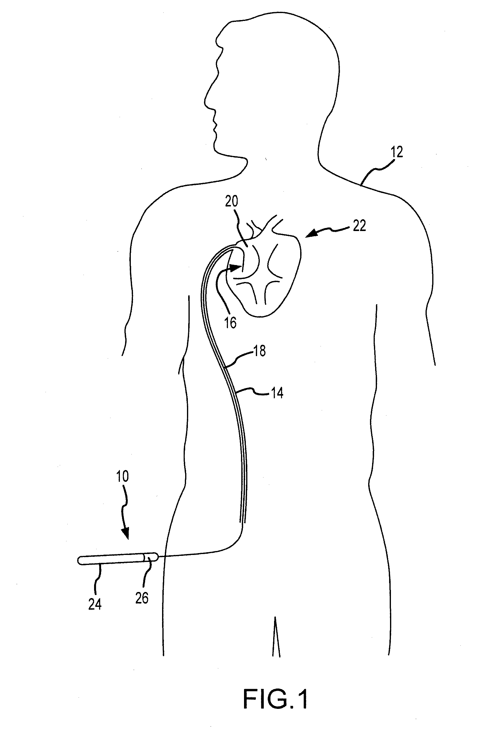
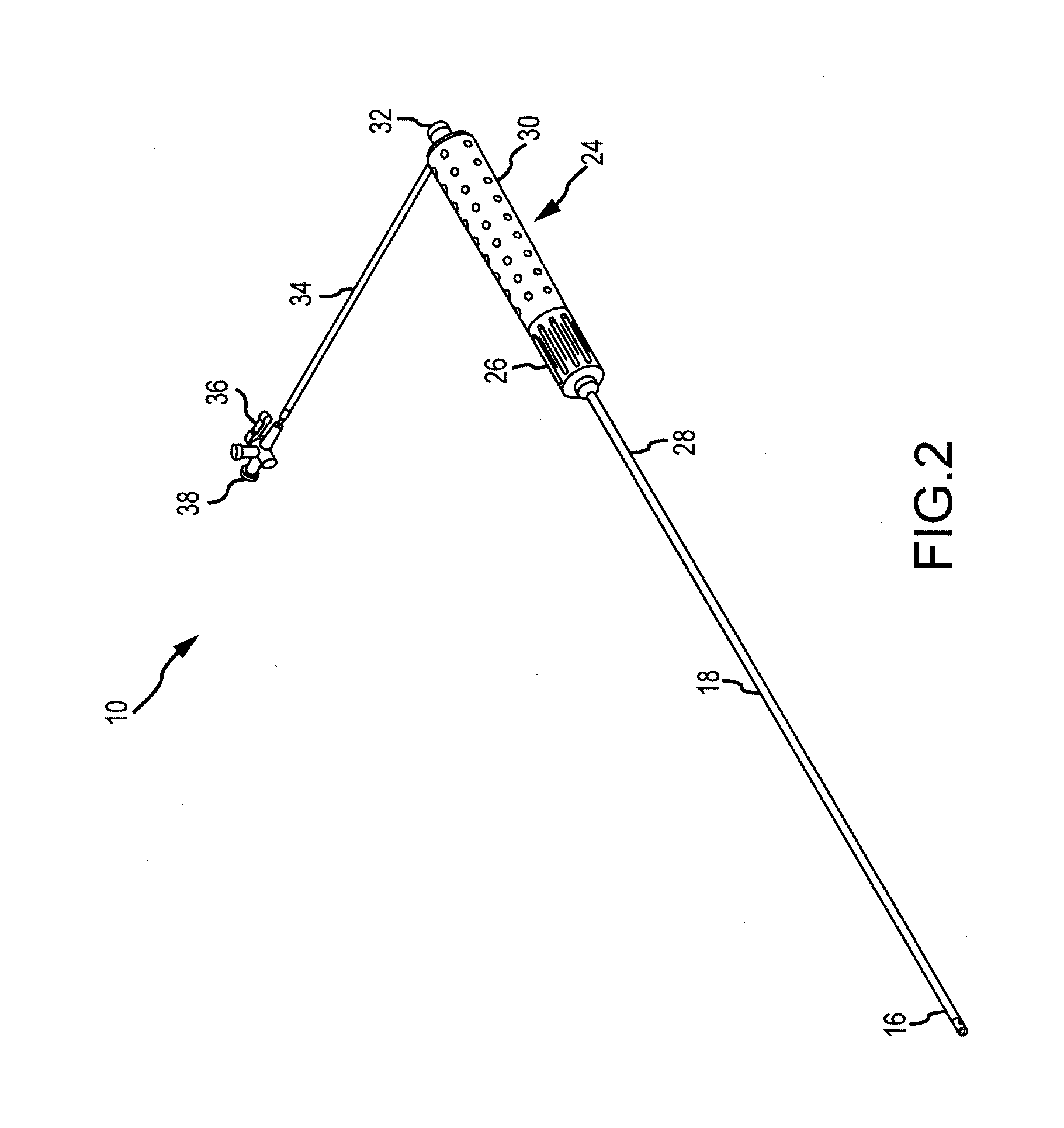
BACKGROUND[0001]a. Technical Field[0002]The instant disclosure relates to handle assemblies for elongate medical devices, including interior components of a handle assembly for resisting deflection of the shaft of the medical device.[0003]b. Background Art[0004]Catheters are used for an ever-growing number of procedures. For example, catheters are used for diagnostic, therapeutic, and ablative procedures, to name just a few examples. Typically, the catheter is manipulated through the patient's vasculature and to the intended site, for example, a site within the patient's heart. The catheter typically carries one or more electrodes, which may be used for ablation, diagnosis, or the like. Often, another medical device, called an introducer or sheath, is used to position a catheter within the heart.[0005]To increase the ability to move and navigate an introducer or catheter within a patient's body, steerable introducers and catheters have been designed. Such steerable devices often hav...

Claims


Application Information

Patent Timeline
Patent Type & Authority Applications(United States)
IPC IPC(8): A61B17/00
CPCA61B17/00A61B18/1492A61M25/0136A61N7/022A61B2018/0091A61B2018/0212A61M25/0147
Inventor BLASKOWSKI, STACIE MARIEANDERSON, STEVEN ANDREAS
Owner ST JUDE MEDICAL ATRIAL FIBRILLATION DIV
Learn More