
Method for detecting motion of input body and input device using same

a technology of input body and input device, which is applied in the direction of static indicating device, image enhancement, instruments, etc., can solve the problems of large-scale and expensive facilities in many cases, unnatural motion of hands of unskilled manipulators, and unnatural hand motion of hands, etc., to improve flexibility of placement of the above-mentioned image sensor, simple facilities, and low cost

Inactive Publication Date: 2014-08-14
NITTO DENKO CORP
View PDF6 Cites 41 Cited by
  • Summary
  • Abstract
  • Description
  • Claims
  • Application Information

AI Technical Summary

Benefits of technology

The present invention provides an input device that can detect three-dimensional motion using a single image sensor. This leads to simple and low-cost facilities. The flexibility of placement of the image sensor is improved, allowing it to be placed in a position that an operator is unaware of. This results in an intuitive and user-friendly device that even a novice can easily operate.

Problems solved by technology

However, the three-dimensional position measurement system for use in the aforementioned conventional input device necessarily involves the need for a plurality of cameras, which results in large-scale and costly facilities in many cases.
In addition, the cameras are not always disposed in positions optimum for shooting, depending on the ambient environment and the device structure thereof, but are disposed in positions which give a feeling of strangeness to an operator.
Further, when the cameras come into a field of view recognizable by the operator, there is apprehension that the motion of a hand of the person unskilled in manipulation is unnatural or is not smooth.

Method used


Image

  • Method for detecting motion of input body and input device using same
  • Method for detecting motion of input body and input device using same
  • Method for detecting motion of input body and input device using same

Examples


Embodiment Construction

[0022]Next, an embodiment according to the present invention will now be described in detail with reference to the drawings. It should be noted that the present invention is not limited to the embodiment.

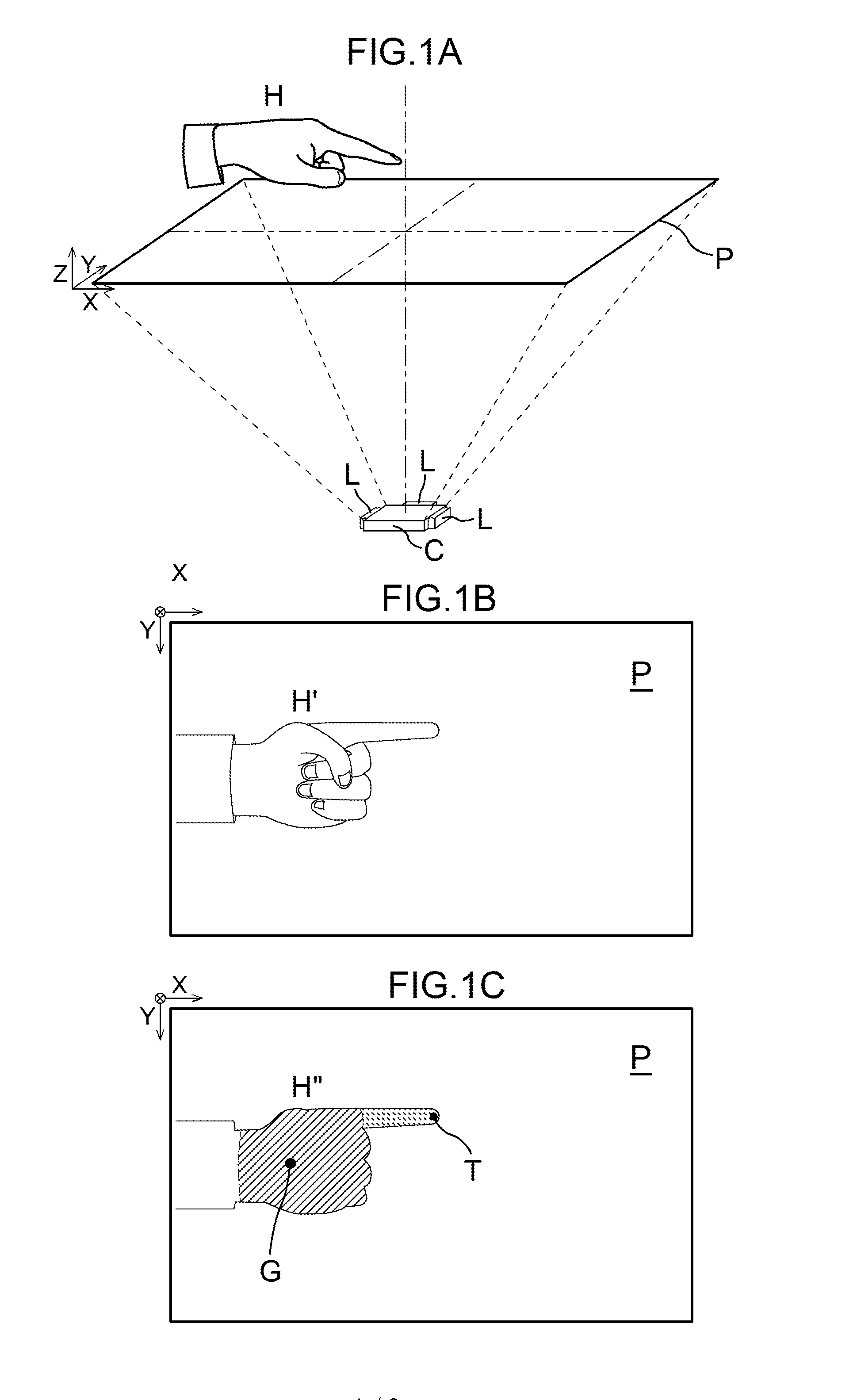
[0023]FIG. 1A is a view illustrating a method for detecting the coordinates of a hand H in an input device according to the embodiment of the present invention. FIG. 1B is a schematic view of a two-dimensional (virtual imaging plane P) image H′ shot with an optical imaging means (camera C) in the aforementioned input device. FIG. 1C is a schematic view of an image H″ obtained by binarizing the two-dimensional image H′ of the aforementioned hand H. In subsequent figures including FIG. 1, a computer having the functions of a control means for controlling the camera C and light sources L, a shape recognition means, a motion determination means and the like, and connected to the aforementioned camera C is not shown.

[0024]The input device according to the present embodiment is provided f...


PUM


Abstract

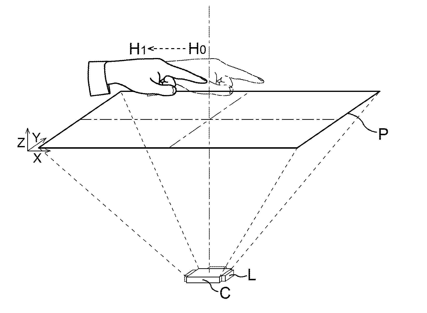
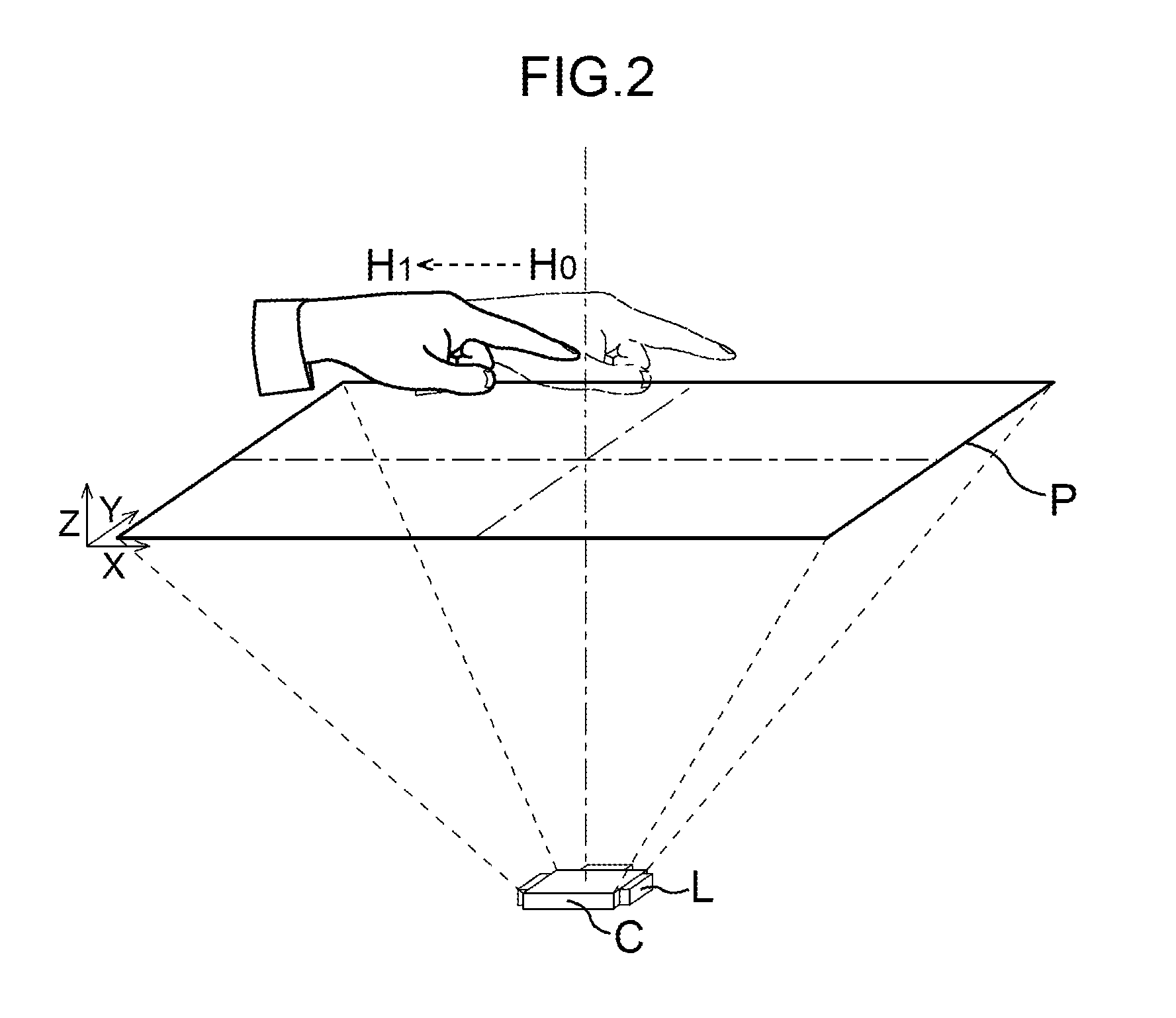
An input device includes: a light source; an image sensor (camera C) disposed on the same side of a hand as the light source; a controller; a shape recognizer for calculating coordinates of the center of gravity of a fist and the tip of a finger from a two-dimensional image; and a motion determinator for comparing distances between the center of gravity of the fist and the fingertip. When there is a decrease or an increase between the distances between the center of gravity of the fist and the fingertip before and after measurement, a determination is made that the motion is an upward or downward motion of the finger with respect to a virtual imaging plane of the camera. This provides a method for detecting motion of an input body, capable of detecting the motion of a hand from image analysis by using the single image sensor.

Description

TECHNICAL FIELD[0001]The present invention relates to a method for detecting the motion of a hand used for input of coordinates in an input device, and the input device using the same.BACKGROUND ART[0002]An input device which uses a human hand, a human finger and the like as an input body for manipulation has been developed as a user interface for a device capable of interaction with a two-dimensional video picture or a three-dimensional video picture which is displayed. This input device includes a three-dimensional position measurement system having a plurality of optical imaging means such as cameras. Based on images (two-dimensional images) obtained from the cameras whose shooting position and shooting angle are determined, this input device calculates the three-dimensional position, the coordinates on three axes (X, Y and Z axes) and the like of an object (input body) of interest by computation to output the coordinate values thereof to a control means (such as a computer) of a...

Claims


Application Information

Patent Timeline
IPC IPC(8): G06F3/01G06K9/00G06T7/20G06F3/03
CPCG06F3/017G06T7/20G06K9/00355G06F3/0304G06F2203/04101G06F3/0425G06T2207/30196G06T7/246G06V40/28
Inventor JUNI, NORIYUKI
Owner NITTO DENKO CORP
Learn More