Motor control system

a technology of motor control and control system, which is applied in the direction of electric generator control, dynamo-electric converter control, dynamo-electric gear control, etc., can solve the problems of motor loss reduction, motor loss increase, and loss in converter and inverter increas

Active Publication Date: 2014-08-14
TOYOTA JIDOSHA KK +1
View PDF4 Cites 10 Cited by
  • Summary
  • Abstract
  • Description
  • Claims
  • Application Information

AI Technical Summary

Benefits of technology

The invention enables a motor control system to control multiple motors with a single converter. It prevents interference between feedback controls for the motors, allowing for stable and smooth control of the system voltage. This ensures that the motors operate without interruptions and at optimal efficiency.

Problems solved by technology

However, because rectangular wave control is voltage phase control under field-weakening control, a motor loss increases as a field-weakening current increases: On the other hand, when a voltage stepped up by the converter is increased to operate the alternating-current motor in sinusoidal PWM control, a motor loss is reduced.
However, due to a switching, loss resulting from an increase in the number of switching operations, a loss in the converter and the inverter increases.
However, in the case where feedback loops of the current vectors, or the like, are respectively provided in correspondence with the individual motors, when the motor and a feedback control deviation are not appropriately selected, the plurality of feedback controls interfere with each other and as a result, variable control of the system voltage may be unstable or the system voltage may become stepwise, which hinders smooth variable control.

Method used


Image

  • Motor control system
  • Motor control system
  • Motor control system

Examples


Embodiment Construction

[0039]Hereinafter, embodiments according to the invention (hereinafter, embodiments) will be described in detail with reference to the accompanying drawings. In the description, shapes, materials, numeric values, directions, and the like, are illustrative for the sake of easy understanding of the invention, and may be modified as needed in accordance with an application, a purpose, specifications, and the like. In addition, when a plurality of embodiments, alternative embodiments, and the like, are included in the following description, it is originally assumed to use characterizing portions of them in combination where appropriate.

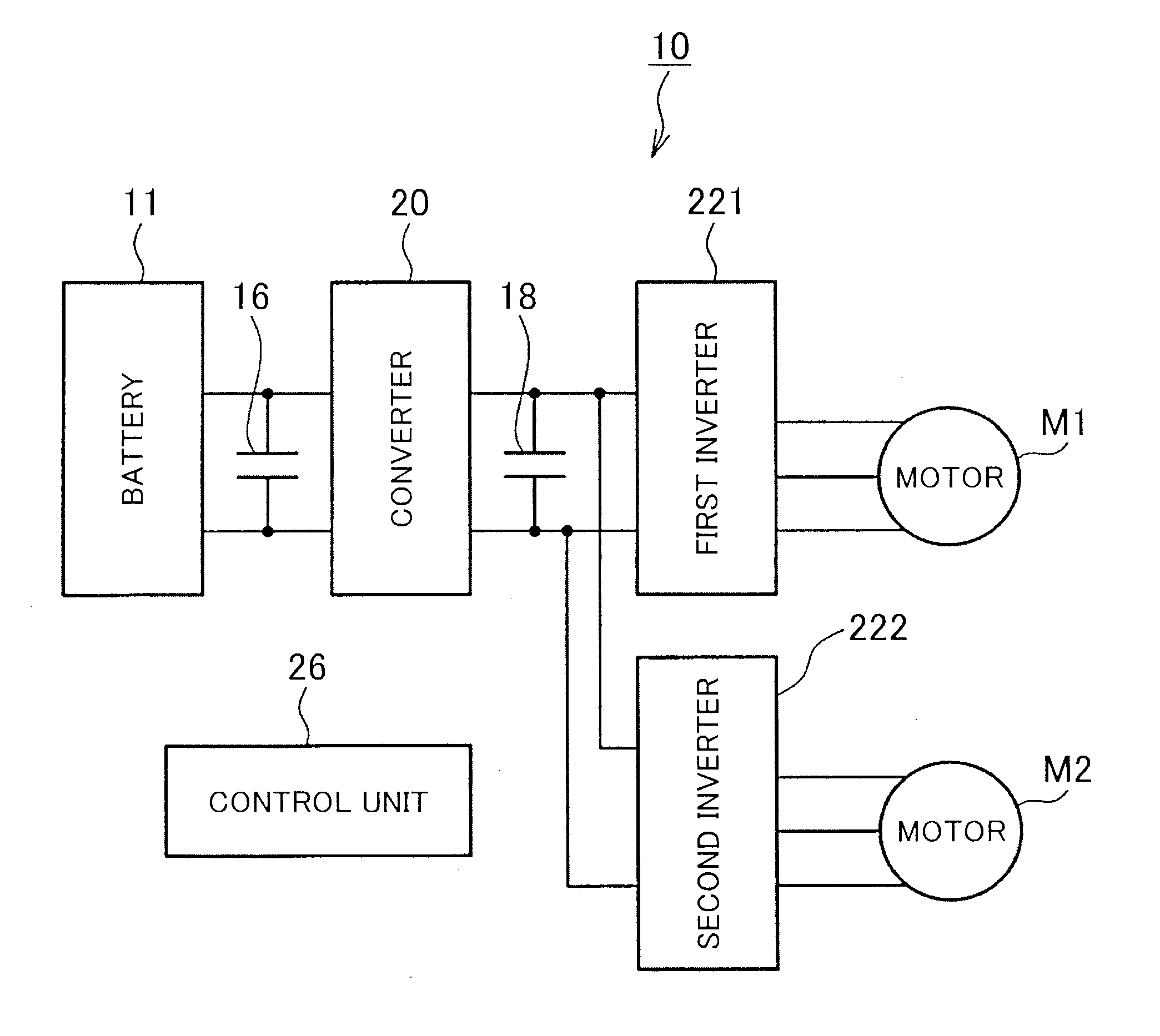
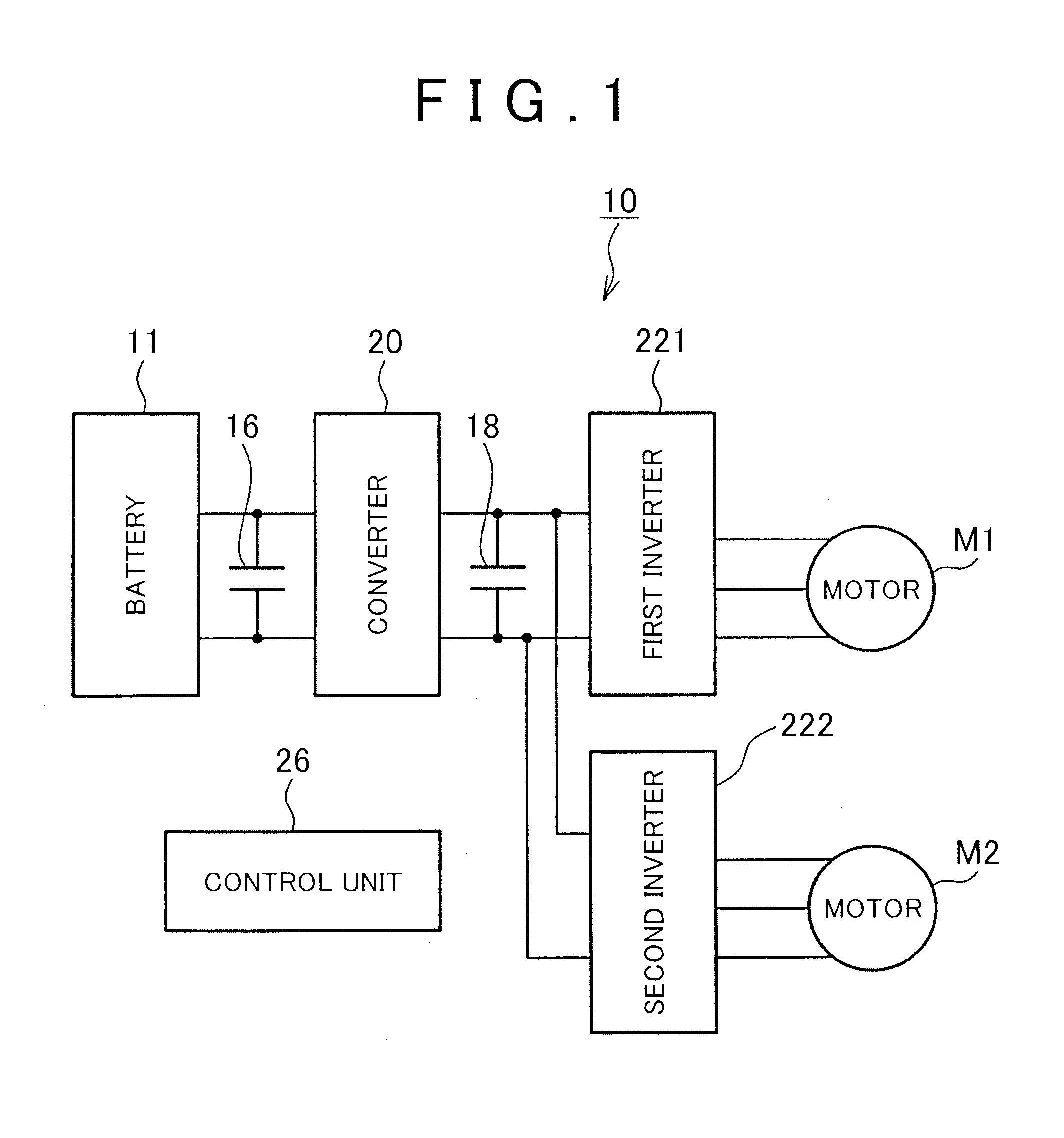
[0040]FIG. 1 is a diagram that shows an overall configuration of a motor control system 10 according to an embodiment. The motor control system 10 may be suitably used in a hybrid vehicle, an electric vehicle, or the like, on which an electric motor is mounted as a driving power source.

[0041]The motor control system 10 includes a battery 11, a converter 2...


PUM


Abstract

A motor control system includes: a converter; two inverters; two alternating-current motors; and a control unit. The control unit is configured to control the system voltage by feedback of a current phase of a current vector of motor current of each of the motors on a d-q coordinate plane so that rectangular wave control of at least one of the first and second motors is performed in a state where the current phase is an optimal current phase, wherein the control unit selects, as a subject of the feedback, the current phase of one of the motors that is larger than the other motor in system voltage deviation obtained based on the current vector.

Description

BACKGROUND OF THE INVENTION[0001]1. Field of the Invention[0002]The invention relates to a motor control system and, more particularly, to a motor, control system that executes drive control of an alternating-current motor by applying alternating-current voltage converted by an inverter from direct-current voltage stepped up by a converter.[0003]2. Description of Related Art[0004]In a related art, there is known an electric vehicle that includes an electric motor as a driving power source. The electric motor is driven by electric power from a battery to output power. A three-phase synchronous alternating-current motor may be used as the electric motor. The three-phase synchronous alternating-current motor is driven by the application of three-phase alternating-current voltage converted by an inverter from direct-current voltage supplied from a power supply.[0005]In addition, in some electric vehicles as described above, the direct-current voltage supplied from the battery is not dir...

Claims


Application Information

Patent Timeline
IPC IPC(8): H02P6/04H02P21/00B60L3/00B60L9/18H02M7/48H02P5/54H02P5/74H02P6/06H02P6/08H02P6/17H02P6/28H02P21/22H02P27/04H02P27/08
CPCH02P6/04H02P2006/045H02P21/0035B60L15/02H02P27/06H02P2201/09H02P23/009H02P21/22Y02T10/64H02P5/68
Inventor YAMADA, KENJINAKAI, YASUHIRO
Owner TOYOTA JIDOSHA KK
Why Eureka
Try Eureka