
Control device for bicycle and methods

a control device and bicycle technology, applied in the field of bicycle control systems, can solve the problems of increasing complexity and weight, affecting the safety of users, and affecting the safety of users, and achieve the effect of convenient transportation from the bik

Active Publication Date: 2014-07-31
SRAM CORPORATION
View PDF10 Cites 50 Cited by
  • Summary
  • Abstract
  • Description
  • Claims
  • Application Information

AI Technical Summary

Benefits of technology

The patent text is talking about a system where each shift control device has its own battery to eliminate the need for wires and connectors. The technical effect of this system is that it makes each control device more efficient and reliable because it doesn't have to rely on a central power source.

Problems solved by technology

Operating such devices during activities which require concentration and control such as riding a bike can be hazardous.
This requires structure to mount the shifter to the bar which increases weight.
The shifters may all be linked by cables or wires which adds complexity and weight.
Alternatively, they may all be discretely wireless, which requires separate power sources for each device adding weight and complexity.

Method used


Image

  • Control device for bicycle and methods
  • Control device for bicycle and methods
  • Control device for bicycle and methods

Examples


Embodiment Construction

[0036]Embodiments of the invention will herein be described with reference to the drawings. It will be understood that the drawings and descriptions set out herein are provided for illustration only and do not limit the invention as defined by the claims appended hereto and any and all their equivalents. For example, the terms “first” and “second,”“front” and “rear,” or “left” and “right” are used for the sake of clarity and not as terms of limitation. Moreover, the terms refer to bicycle mechanisms conventionally mounted to a bicycle and with the bicycle oriented and used in a standard fashion unless otherwise indicated.

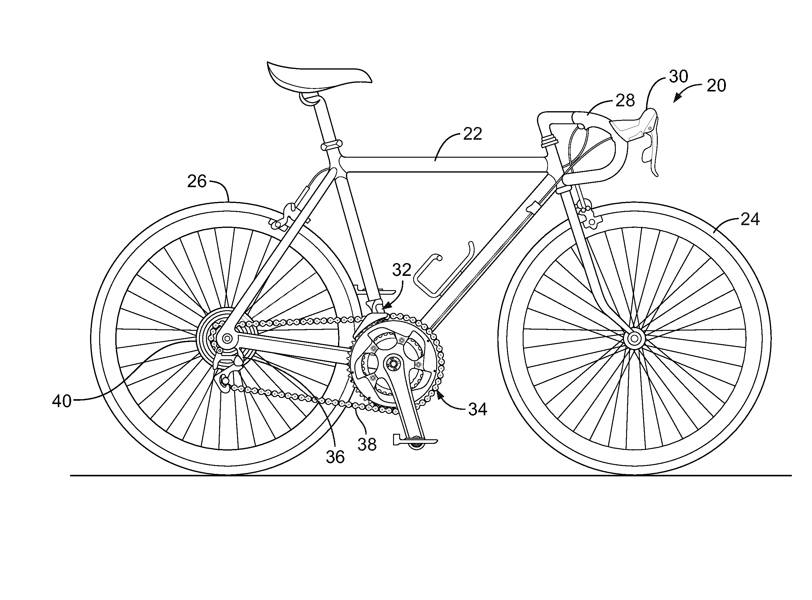
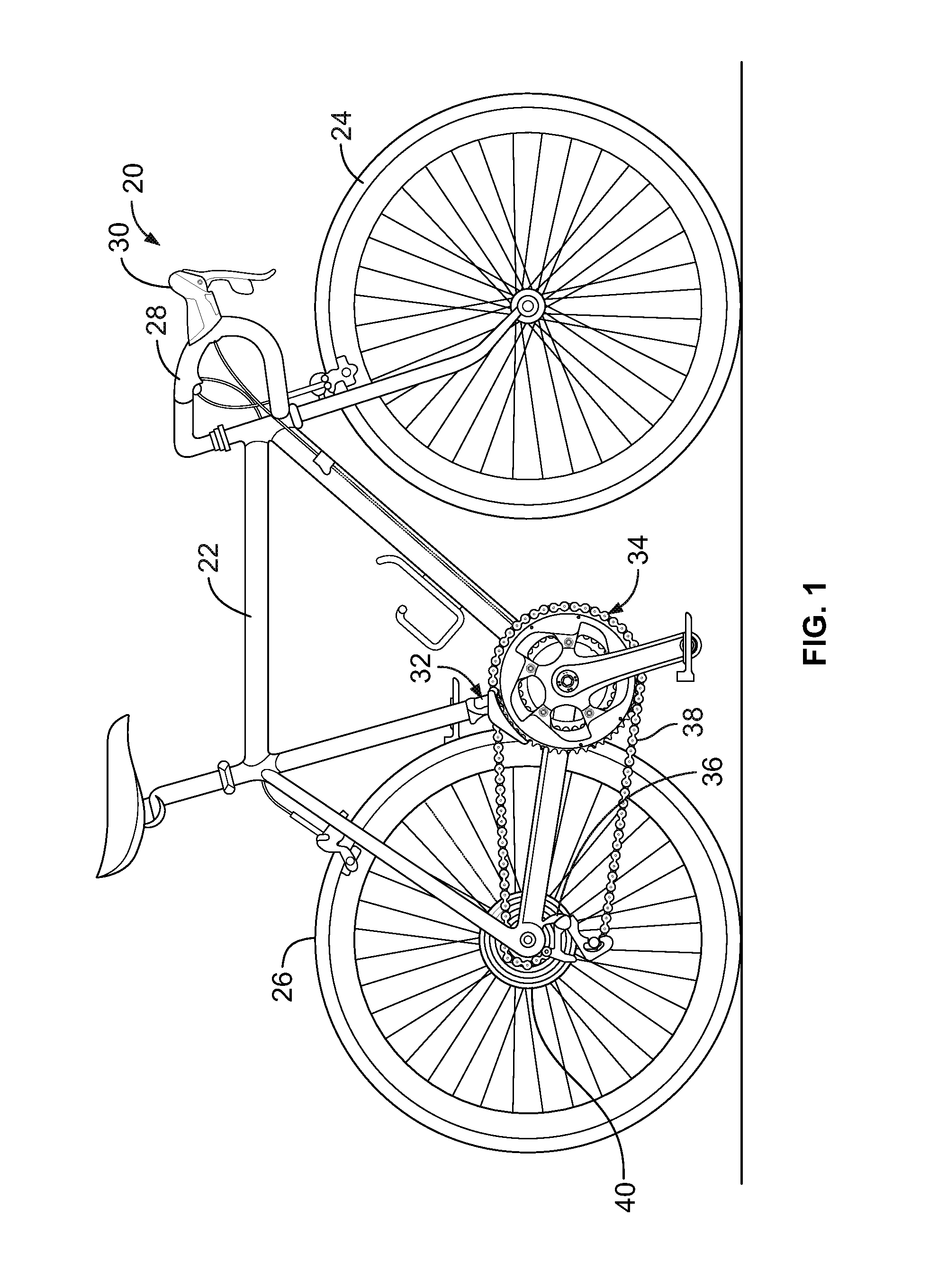
[0037]FIGS. 1 and 16 show a bicycle 20 having a frame 22 to which a front wheel 24 and a rear wheel 26 are attached in conventional positions. A handlebar 28 is attached near the front of the bicycle 20 and a pair of brake actuators 30 is attached to the handlebar. A front derailleur 32 may be attached to the frame 22 at or near a front crankset / chainring assembly 3...


PUM


Abstract

A control device wearable by a bicycle rider, the control device including at least one control sensor generating input signals when actuated. A control processor is connected to the at least one control sensor generating control signals responsive to the input signals. A wireless transmitter is in communication with the processor transmitting the control signals and a power source is connected to the shift control processor and the wireless transmitter. The control device may one or more of a control gear changer, one or more suspension component, and other electronically-controllable components or systems.

Description

BACKGROUND OF THE INVENTION[0001]The invention relates to bicycle control systems. In particular, the invention is directed to systems including wirelessly enabled controllers for bicycle gear changers and / or bicycle suspensions and other bicycle components and systems.[0002]Electronic devices and wireless communication are common in modern society. Operating such devices during activities which require concentration and control such as riding a bike can be hazardous. This is because the user input for the control is traditionally mounted to the handlebar of a bike. In some instances, in well-designed controllers, the rider's hands are close to the control switches so activating the control switches poses little danger. However, in the case where the rider has their hands in a location remote from the control switches, the rider must then shift one hand to the control switch and temporarily control the bike with the remaining hand. Additionally, should the rider wish to operate the ...

Claims


Application Information

Patent Timeline
IPC IPC(8): F16H59/02
CPCF16H59/02F16H59/68B62M25/08B62M9/132B62M9/122B62J45/414B62M25/045B62K23/02G06F3/014G06F1/163
Inventor WESLING, KEVIN
Owner SRAM CORPORATION
Learn More