Ink jet printing apparatus
a printing apparatus and jet technology, applied in printing and other directions, can solve the problem that foreign substances attached to the top face of the distal end cannot be easily removed, and achieve the effect of improving the quality of printing
- Summary
- Abstract
- Description
- Claims
- Application Information
AI Technical Summary
Benefits of technology
Problems solved by technology
Method used
Image
Examples
first embodiment
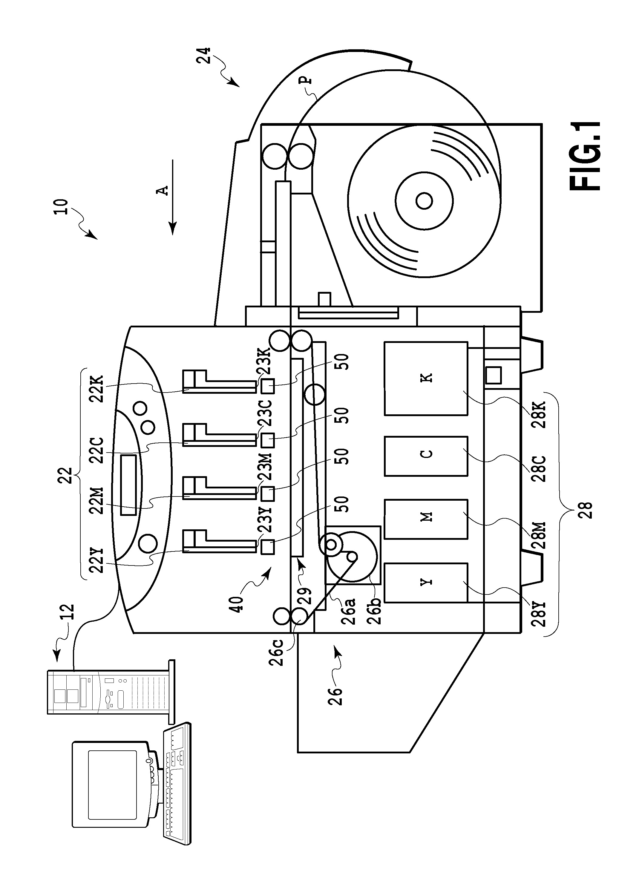
[0025]FIG. 1 is a schematic front view of an ink jet printing apparatus according to a first embodiment of the invention. A printing apparatus 10 in this embodiment is a full-line type printer, and is connected to a host PC (host apparatus) 12. Based on printing information received from the host PC 12, four print heads 22 (22K, 22C, 22M and 22Y) of the printing apparatus 10 eject black, cyan, magenta and yellow inks, respectively, to print an image to rolled paper (printing medium) P.
[0026]The print heads 22 are elongate heads that are extended across an entire printing area of the rolled paper P in a widthwise direction, and in a direction that crosses a conveying direction A of the rolled paper P (in this embodiment, a perpendicular direction). The print head 22K that ejects black ink, the print head 22C that ejects cyan ink, the print head 22M that ejects magenta ink and the print head 22Y that ejects yellow ink are arranged in the named order in the conveying direction A. For e...
second embodiment
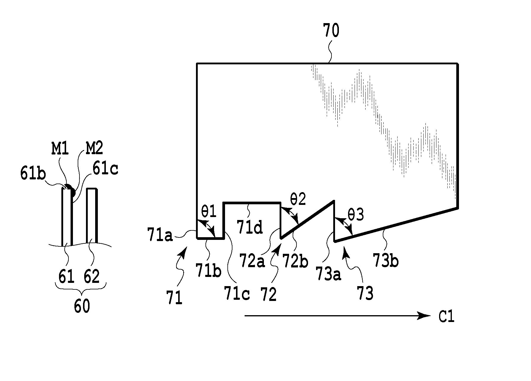
[0043]FIG. 6 is a diagram for explaining an operation for cleaning the blade 60 for a second embodiment of the present invention, but an explanation will not be given for the same process steps as those for the first embodiment.
[0044]Part (a) of FIG. 6 shows the state wherein, after the same process beginning from part (a) to part (e) of FIG. 5 in the first embodiment has been performed, the first blade 61 is moved in the direction indicated by the arrow C1 with the top face 61 sliding across the inclined face 73b. Thereafter, a movement of the blade cleaner 70 in a direction indicated by an arrow D (parts (b), (d), (f), (h) and (j) of FIG. 6) and the movement of the first blade 61 in the direction indicated by the arrow C1 (parts (c), (e), (g) and (i) of FIG. 6) are alternately performed. When the blade cleaner 70 is moved away from the first blade 61, step by step, in the direction indicated by the arrow D in this manner, a state wherein the top face 61b of the first blade 61 is o...
third embodiment
[0046]FIG. 7 is a diagram for explaining an operation for cleaning the blade 60 for a third embodiment of the present invention, but an explanation will not be given for the same process steps as those for the first embodiment.
[0047]Part (a) of FIG. 7 shows the state wherein, after the same process beginning from part (a) to part (e) of FIG. 5 in the first embodiment has been performed, the first blade 61 is moved in the direction indicated by the arrow C1 with the top face 61 sliding across the inclined face 73b. Thereafter, a movement of the blade cleaner 70 in a direction indicated by an arrow E (parts (b), (d), (f), (h) and (j) of FIG. 7) and the movement of the first blade 61 in the direction indicated by the arrow C1 (parts (c), (e), (g), (i) and (k) of FIG. 7) are alternately performed. When the blade cleaner 70 is gradually moved, in this manner, in the direction indicated by the arrow E to contact the first blade 61, a state wherein the top face 61b of the first blade 61 is...
PUM
 Abstract
Description
Claims
Application Information
 - R&D
- Intellectual Property
- Life Sciences
- Materials
- Tech Scout
- Unparalleled Data Quality
- Higher Quality Content
- 60% Fewer Hallucinations
Browse by: Latest US Patents, China's latest patents, Technical Efficacy Thesaurus, Application Domain, Technology Topic, Popular Technical Reports.
© 2025 PatSnap. All rights reserved.Legal|Privacy policy|Modern Slavery Act Transparency Statement|Sitemap|About US| Contact US: help@patsnap.com


